-
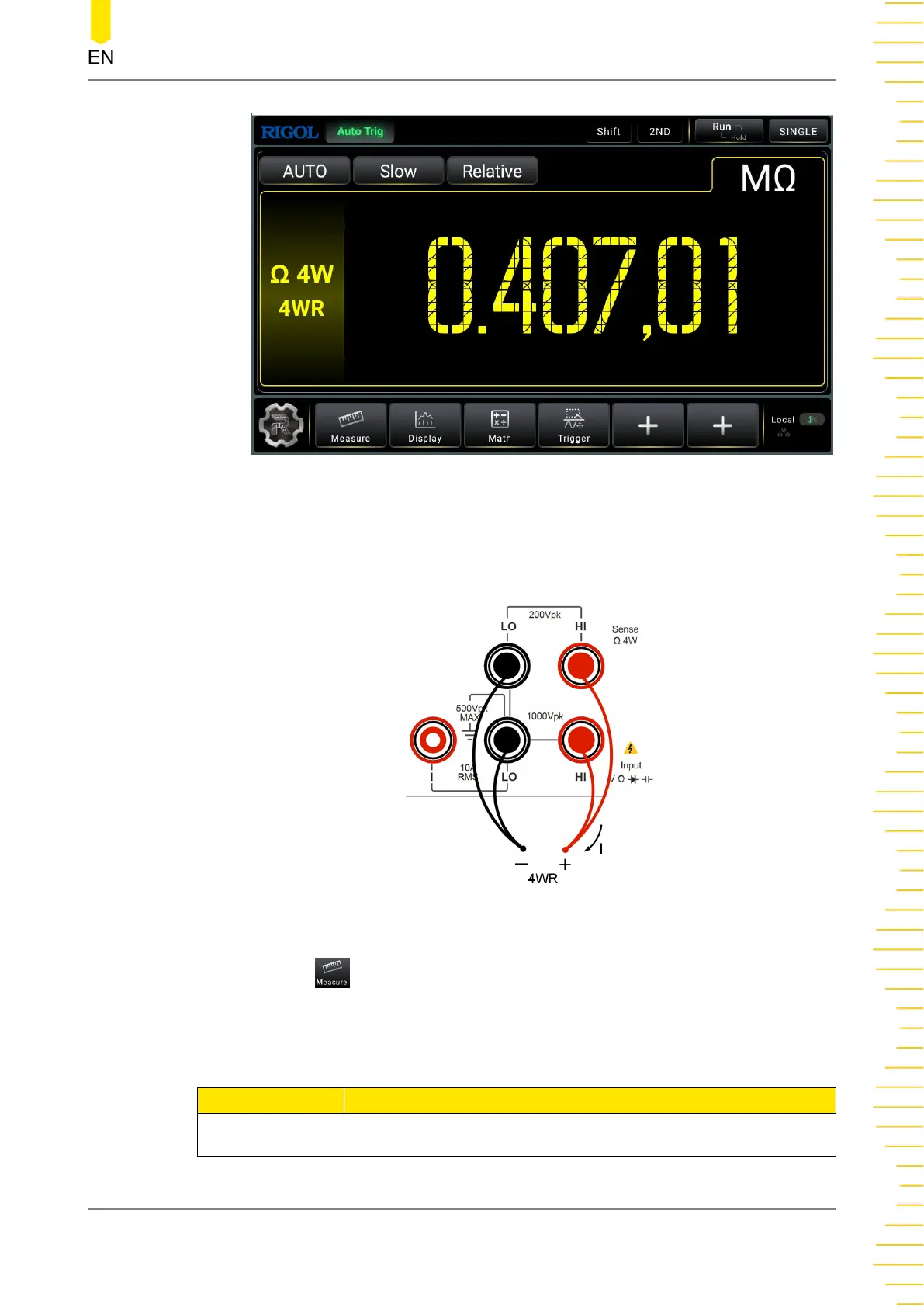
Figure 5.13 4WR Measurement Interface
2. Connect red leads to terminal Input-HI and HI-Sense, black leads to terminal
Input-LO and Low Sense, as shown in the figure below.
Figure 5.14 4WR Measurement Connection Diagram
3. Click or tap to set the measurement range, rate, and display digit (available
when the range is set to 1 MΩ or above).
Table 5.7 4WR Measurement Parameter
Parameter Description
Range* Auto, 100 Ω, 1 kΩ, 10 kΩ, 100 kΩ, 1 MΩ, 10 MΩ, and 100 MΩ
Front Panel Operation
Copyright ©RIGOL TECHNOLOGIES CO., LTD. All rights reserved. DM858 Series User Guide
45