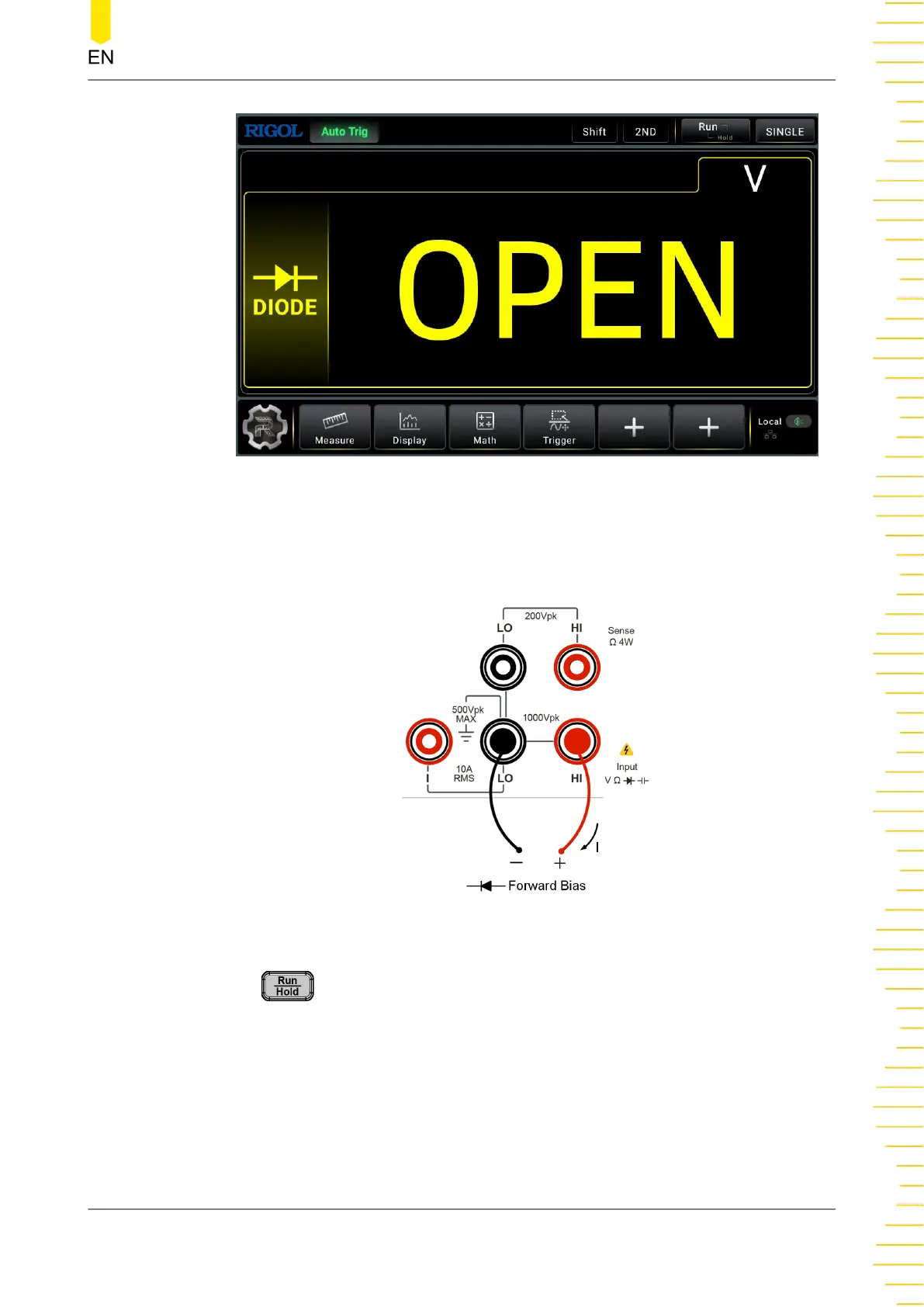
Figure 5.19 Diode Measurement Interface
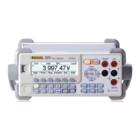
2. Connect red lead to both terminal Input-HI and anode of the Diode and black lead
to both terminal Input-LO and cathode of the Diode, as shown in the figure below.
Figure 5.20 Diode Measurement Connection Diagram
3. Press on the front panel, and the secondary display area is displayed. Click
or tap the ON/OFF tab for Beeper to enable or disable the beeper. When the diode
is properly connected, the instrument beeps for one time (If beeper is enabled).
4. Different conditions for Measurement Result:
Front Panel Operation
Copyright ©RIGOL TECHNOLOGIES CO., LTD. All rights reserved. DM858 Series User Guide
51