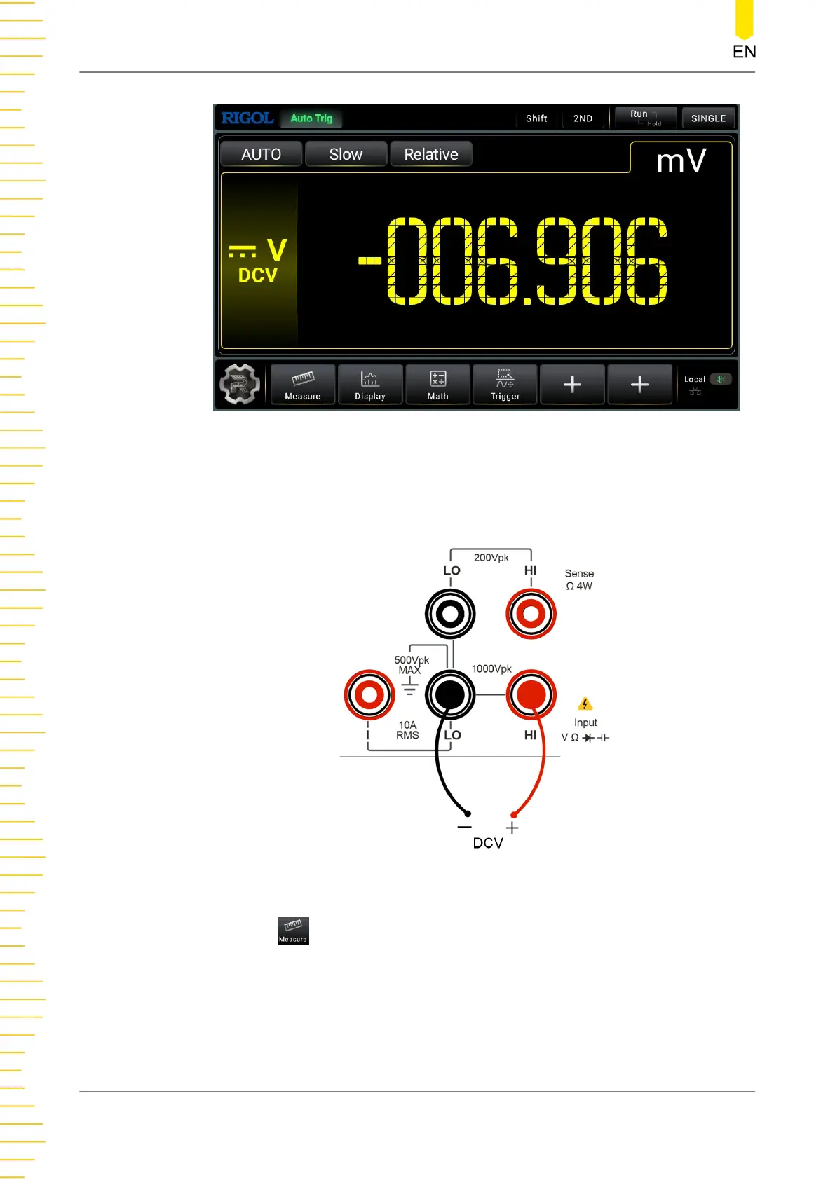
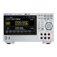
Figure 5.3 DC Voltage Measurement Interface
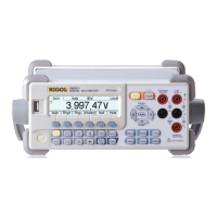
2. Connect red lead to terminal Input-HI and black lead to terminal Input-LO, as
shown in the figure below.
Figure 5.4 DC Voltage Measurement Connection Diagram
3. Click or tap to set the measurement parameters of DC voltage: Range,
Impedance (available to set when the Range is not set to Auto), and Rate.
Front Panel Operation
DM858 Series User Guide
34
Copyright ©RIGOL TECHNOLOGIES CO., LTD. All rights reserved.