195
Effects List
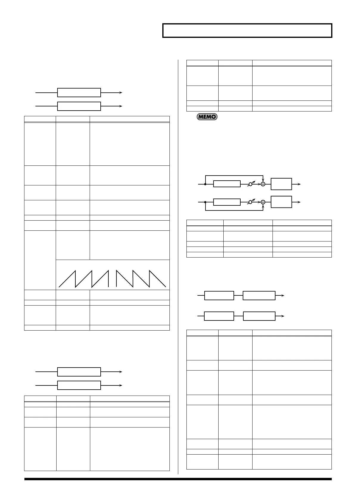
05: SUPER FILTER
This is a filter with an extremely sharp slope. The cutoff frequency
can be varied cyclically.
fig.MFX-05
06: STEP FILTER
This is a filter whose cutoff frequency can be modulated in steps. You
can specify the pattern by which the cutoff frequency will change.
fig.MFX-06
You can use multi-effect control to make the step sequence play
again from the beginning (p. 215).
07: ENHANCER
Controls the overtone structure of the high frequencies, adding
sparkle and tightness to the sound.
fig.MFX-07
08: AUTO WAH
Cyclically controls a filter to create cyclic change in timbre.
fig.MFX-08
Parameter
Value Description
Filter Type
LPF, BPF, HPF,
NOTCH
Filter type
Frequency range that will pass through
each filter
LPF
: frequencies below the cutoff
BPF:
frequencies in the region of the
cutoff
HPF:
frequencies above the cutoff
NOTCH:
frequencies other than the re-
gion of the cutoff
Filter Slope -12, -24, -36 dB Amount of attenuation per octave
-36 dB:
extremely steep
-24 dB:
steep
-12 dB:
gentle
Filter
Cutoff #
0–127 Cutoff frequency of the filter
Increasing this value will raise the cut-
off frequency.
Filter
Resonance #
0–127 Filter resonance level
Increasing this value will emphasize
the region near the cutoff frequency.
Filter Gain 0– +12 dB Amount of boost for the filter output
Modulation
Sw
OFF,ON On/off switch for cyclic change
Modulation
Wave
TRI, SQR, SIN,
SAW1, SAW2
How the cutoff frequency will be modulated
TRI:
triangle wave
SQR:
square wave
SIN:
sine wave
SAW1:
sawtooth wave (upward)
SAW2:
sawtooth wave (downward)
Rate # 0.05–10.00 Hz,
note
Rate of modulation
Depth 0–127 Depth of modulation
Attack # 0–127 Speed at which the cutoff frequency will
change
This is effective if Modulation Wave is
SQR, SAW1, or SAW2.
Level 0–127 Output level
Parameter
Value Description
Step 01–16
0–127 Cutoff frequency at each step
Rate # 0.05–10.00 Hz,
note
Rate of modulation
Attack # 0–127 Speed at which the cutoff frequency
changes between steps
Filter Type LPF, BPF, HPF,
NOTCH
Filter type
Frequency range that will pass
through each filter
LPF:
frequencies below the cutoff
BPF:
frequencies in the region of the
cutoff
HPF:
frequencies above the cutoff
NOTCH:
frequencies other than the re-
gion of the cutoff
L in
R in
L out
R out
Super Filter
Super Filter
SAW1 SAW2
L in
R in
L out
R out
Step Filter
Step Filter
Filter Slope
-12, -24, -36 dB Amount of attenuation per octave
-12 dB:
gentle
-24 dB:
steep
-36 dB:
extremely steep
Filter
Resonance #
0–127 Filter resonance level
Increasing this value will emphasize
the region near the cutoff frequency.
Filter Gain 0– +12 dB Amount of boost for the filter output
Level 0–127 Output level
Parameter
Value Description
Sens # 0–127 Sensitivity of the enhancer
Mix # 0–127 Level of the overtones gener-
ated by the enhancer
Low Gain -15– +15 dB Gain of the low range
High Gain -15– +15 dB Gain of the high range
Level 0–127 Output Level
Parameter
Value Description
Filter Type
LPF, BPF Type of filter
LPF:
The wah effect will be applied
over a wide frequency range.
BPF:
The wah effect will be applied
over a narrow frequency range.
Manual # 0–127 Adjusts the center frequency at which the
effect is applied.
Peak 0–127 Adjusts the amount of the wah effect that
will occur in the range of the center fre-
quency.
Set a higher value for Q to narrow the
range to be affected.
Sens # 0–127 Adjusts the sensitivity with which the fil-
ter is controlled.
Polarity UP, DOWN Sets the direction in which the frequency
will change when the auto-wah filter is
modulated.
UP:
The filter will change toward a
higher frequency.
DOWN:
The filter will change toward
a lower frequency.
Rate # 0.05–10.00 Hz,
note
Frequency of modulation
Depth # 0–127 Depth of modulation
Phase # 0–180 deg Adjusts the degree of phase shift of the
left and right sounds when the wah effect
is applied.
Parameter
Value Description
L in
R in
L out
R out
Mix
Mix
Enhancer
Enhancer
2-Band
EQ
2-Band
EQ
L in
R in
L out
R out
Auto Wah
2-Band EQ
2-Band EQ
Auto Wah
Fantom-XR_r_e.book 195 ページ 2006年4月4日 火曜日 午前10時14分
 Loading...