56 Installation and Maintenance ODIN Intercom Matrix
7. Click the right encoder knob.
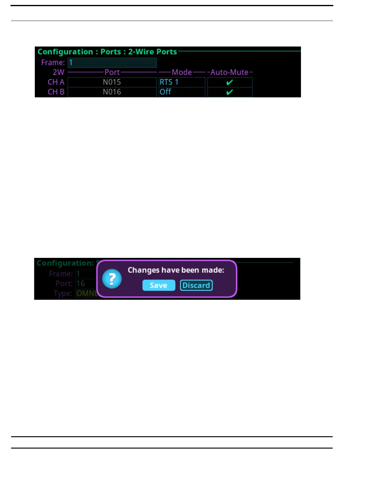
The 2W Channels screen appears.
8. Rotating the right encoder knob, navigate to the Mode field.
9. Click the right encoder knob.
The Mode field becomes active.
10. Rotating the right encoder knob, select the Mode.
11. Click the right encoder knob.
The Mode field is changed.
12. Rotating the right encoder knob, navigate to the Auto-Mute field.
13. Click the right encoder knob.
The Auto-Mute field becomes active.
14. Press the SEL button to enable/disable Auto-Mute.
OR
Click the right encoder knob to disable Auto-Mute.
NOTE: For more information, see “2-Wire” on page 94.
15. Click the right encoder knob.
The Auto-Mute field turns yellow.
16. Click the left encoder knob to exit the screen.
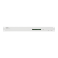
A Changes Made confirmation message appears.
17. Click the right encoder knob to save.
OR
Rotating the right encoder knob, move the focus to Discard, and then click the encoder knob to confirm the discard.
NOTE: Alternately, the left shaft encoder button can be clicked or the CLR button can be pressed to cancel this prompt
and go back to editing on the underlying screen (for example, if the user is not ready to Save or Discard the
modifications).
18. On the back of ODIN, connect the 2W device to the CH A or CH B connector configured in the Port Allocation Table.
Connecting Analog Keypanels to ODIN
To connect an analog keypanel to ODIN, do the following:
1. Using the Port Allocation table, assign the device channel to the AIO port. See, “Allocate Ports from the Front Panel of
ODIN” on page 38.
2. On the back of ODIN, connect the keypanel to the AIO connector.
IMPORTANT: The AIO port assigned in the Port Allocation Table must match the AIO port on the rear panel of ODIN.