SATO M-10e TT/DT Printers Service Manual
PN 9001098
Rev. A
1-4
Section 1. Overview and Specifications
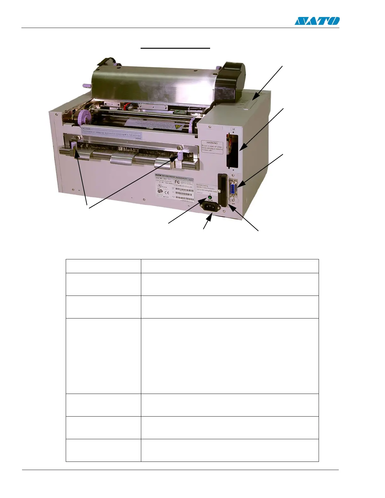
Components
BACK OF PRINTER
PCMCIA
Card Slot
Interface
Card Slot
POWER SWITCH To turn power On or Off
CONFIGURATION
PANEL
Potentiometers and DIP switches to configure the
printer and make setup adjustments.
OPERATOR
PANEL
To set up the various configurations and to display
dispensing quantity and the various alarms.
INTERFACE
CARD SLOT
Slot to plug in an interface adapter. An adapter
must be connected before the printer is
operational. The adapter types available are:
• RS232C Serial I/F Module, DB-25
• IEEE1284 Parallel I/F Module, AMP 57-40360
• Universal Serial Bus I/F Module
• Ethernet 10/100 BaseT I/F Module
• RS-422/485 I/F Module, DB-9
EXT PORT
CONNECTOR
External signal connector, external control of print
cycle.
PCMCIA
CARD SLOT
One slot for optional PCMCIA Cards
AC INPUT
CONNECTOR
Input 115V, 50/60 Hz connector. Use power cable
provided.
Configuration
Panel
EXT Port
Connector
AC Input
Connector
Media Loaded
LED
Media Width
Adjust
Thumbscrews

 Loading...


