PN 9001098
Rev. A
3-9
SATO M-10e TT/DT Printers Service Manual
Section 3. Interface Specifications
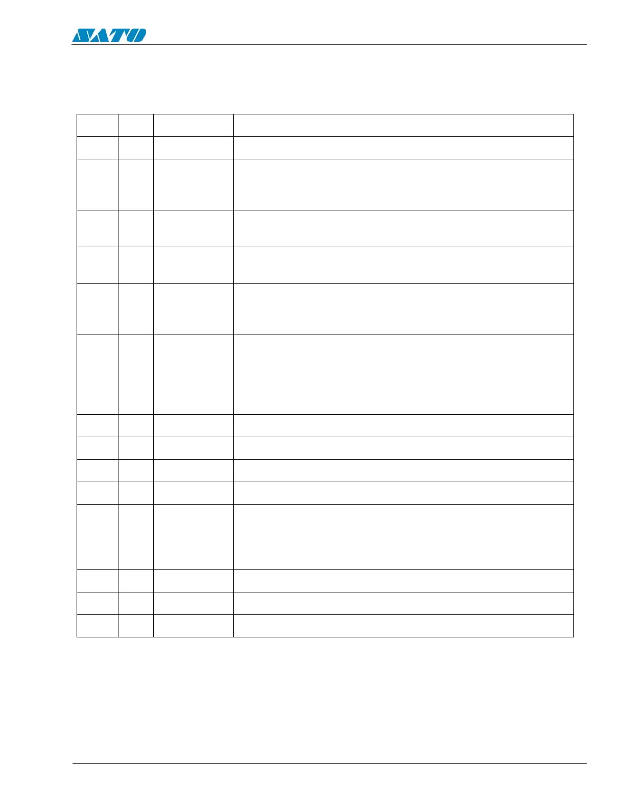
Accessory (EXT) Connector (Cont)
PIN PIN DIRECTION SIGNAL DESCRIPTION
1 13 To Host Vcc -/+5V
210 To Host
Ribbon Near End - This pin goes high when the amount of
ribbon on the unwind shaft is approximately 46 feet (14 m).
The output will be low when the ribbon is completely out.
3 4 To Host Error - This pin goes low when the printer detects an error
condition such as head open or receiving buffer is full.
4 7 To Printer Reprint - A duplicate of the last label in a print job will be
reprinted when this signal is received.
5 5 To Printer
Print Start - The printer will print one label when this pin is
pulled to ground. This signal must be enabled by placing
switch DSW3-5 on the Control Panel in the OFF position.
66 To Host
End Print - It is used to drive an applicator or other external
device requiring synchronization with the print cycle. You
may choose between four types of output signals using
control panel DSW3-6 and DSW3-7 selections. See timing
charts on next page.
7 1 To Host Label Out - This pin goes low (0V) when a label error exists.
8 3 To Host Ribbon Out - This pin goes low (0V) when ribbon is out.
9 2 Reference Signal Ground
8 To Printer Isolated Power Source for signal input.
9To Host
When Mode 1 in LCD selected High Voltage = On-Line Print
Job is waiting.
When Mode 2 in LCD selected High Voltage = On-Line. This
goes low (0V) when printer Off -Line
11 Reserved
12 To Host +24V +/- 10% @2A - Power for external devices
14 Frame Ground
Pin Assignments
Old
DB-9
14 Pin
Centronics

 Loading...


