SATO M-10e TT/DT Printers Service Manual
PN 9001098
Rev. A
3-10
Section 3. Interface Specifications
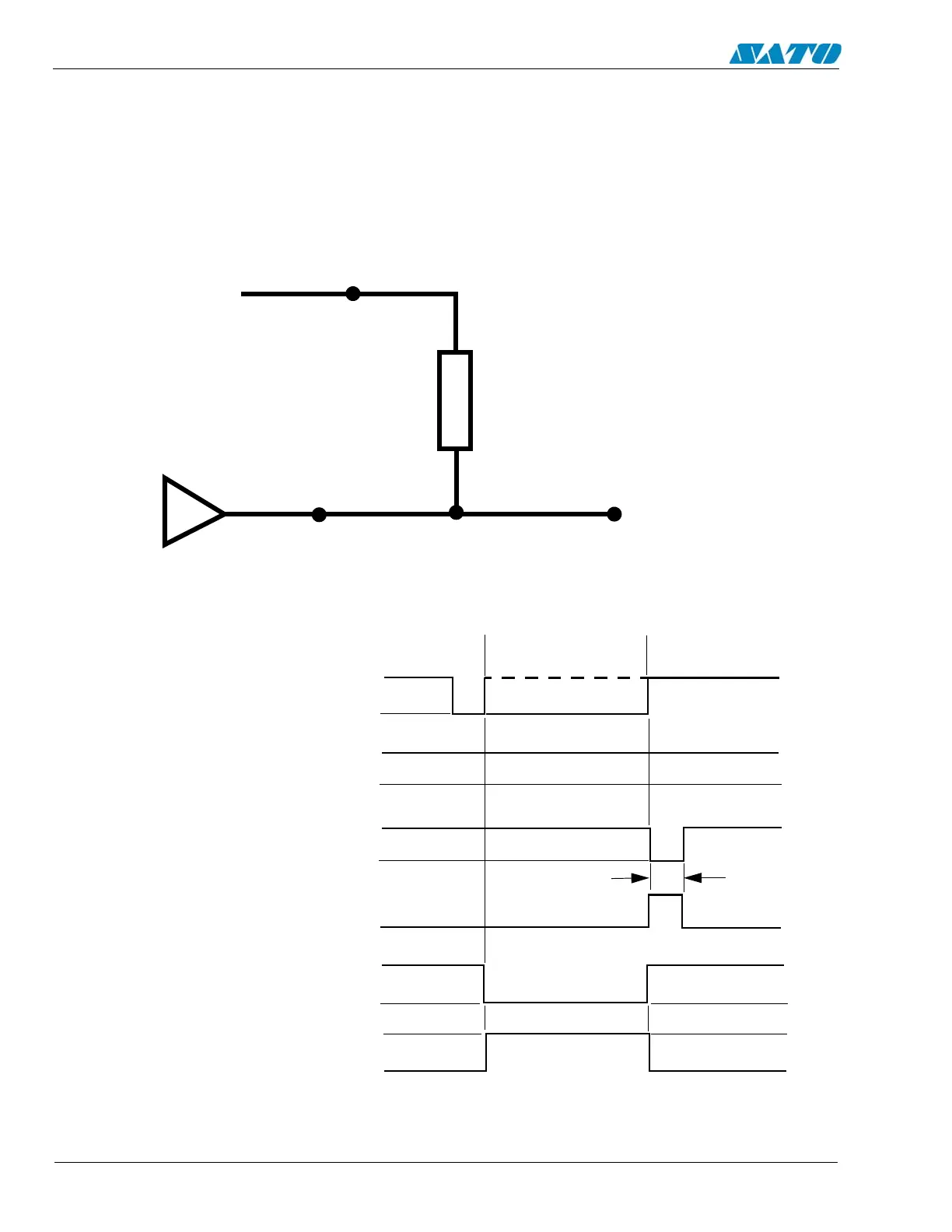
Accessory (EXT) Connector (Cont)
NOTE: The signals on pins 1, 3, 4, 6, 9 and 10 each have an open collector output. Thes pins normally
measure + .07V maximum when a true condition exists. If a false condition occurs, the voltage will drop to
0V. To achieve a signal level of +5V, you must add a 330 ohm, 1/4 W pull-up resistor between the open
collector output pin and Vcc (pin 13) as illustrated. This will provide a signal level of +5V for a true
condition and 0V when a false condition exists. The maximum voltage that can be applied to these pins is
+50V and the maximum current they can sink is 500 milliamps.
Pin 1, 3, 4,
6, 9 or 10
Pin 13
330 ohm, 1/4W
Vcc= +5V
Signal Out
Standard Operation
Start of Print Cycle
End of Print Cycle
Print Start
Input
+5V
0V
Print Repeat
Input
+5V
0V
Print End
Type 1
+5V
0V
Print End
Type 2
+5V
0V
Print End
Type 3
+5V
0V
Print End
Type 4
+5V
0V
20 Milliseconds

 Loading...


