SATO M-10e TT/DT Printers Service Manual
PN 900109
Rev. A
4-14
Section 4. Electrial Checks and Adjustments
4.9 Adjustment of Pitch Correction (Part 1)
STEP PROCEDURE
Refer to Section 4.2 and remove the left side cover for access to the main circuit board.
1. Refer to illustrations and charts on pages 4-5 and 4-16.
Record all current dip switch positions, then place all switches in the OFF position.
2. Align VR9 (PITCH) on the main circuit board and VR3 (PITCH VR) on the top cover to
the center position.
3. Place DSW2-4 in the ON position.
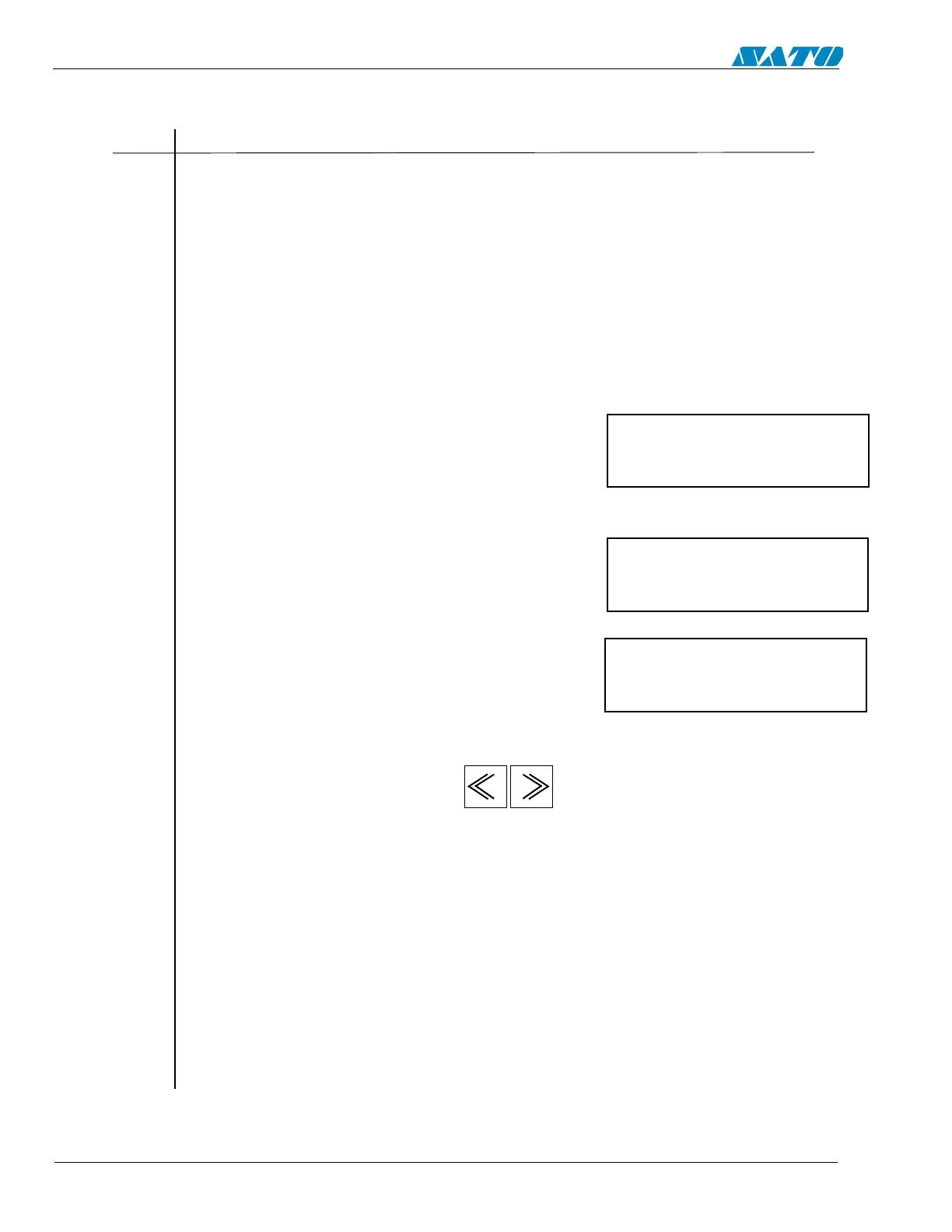
4. Press the LINE and FEED keys simultaneously while turning on the power. Release the
keys when the printer beeps. The following screen will appear.
5. Place the DSW2-4 in the OFF position and the following screen will appear.
6. Press the ENTER key to display the next screen.
7. Check that NONE is displayed and press the ENTER key.
8. Select the print size by pressing the keys. The default is LARGE. Start the
test print by pressing ENTER key.
9. Press the ENTER key once to stop the printing and ENTER again to resume.
Warning: This test activates all the heating elements on the print head and therefore should
be used only for testing purposes with full width labels to avoid damaging the print head.
10. Use the scale of the test print to check for print skew, and then adjust using VR9 (PITCH)
on the main circuit board.
11. Stop the test print using the ENTER key and power OFF the printer.
The scale of the test print is to be at the beginning of the label.
The VR9 (PITCH) adjustment range is +/- 3.75mm.
maintenance mode
dipsw2-4 on>off
factory mode
counter mode
none

 Loading...


