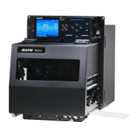
Timing Chart of the EXT Input/Output Signal
550
Pin No.
25-
pin
14-
pin
I/O Description Electric Conditions
(Voltage, Current (Max))
24 13 Input
IN_COM
1
Power supply from peripherals
5 V - 24 V or GND
25 - -
GND
Reference Signal Ground
-
1
When using the 14-pin conversion cable, do not connect the power pin to "IN_COM" pin. The "IN
COM" pin is connected to 5 V in cable.
2
These input signal terminals can be connected to the open collector input devices.
3
If 25-pin is selected, the total output of Pin No. 2 and 12 will be 600 mA.
• You can set the pin number for input and output through the [Settings] > [Interface] >
[External I/O] > [Signals] > [Inputs] and [Outputs] menu.
Timing Chart of the EXT Input/Output Signal
Refer to the programming references regarding the timing chart for the input signal and the output
signal.
For programming references, contact your SATO sales representative or technical support.

 Loading...