Saia-Burgess Controls AG
Manual I/O-modules for PCD1 │ PCD2 series │ Document 27-600 – Release ENG09 │ 2019-05-01
5-99
I/O modules PCD1|PCD2
PCD2.W525 Combined analogue input/output module with galvanic isolation
5
Conguration
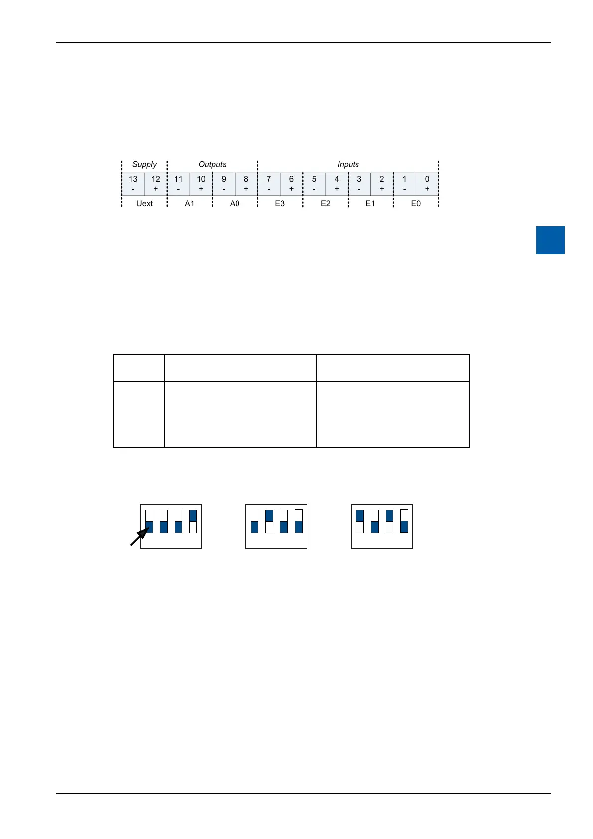
Module connections/LED
The connections of the module terminal are the following:
Description of the LED:
● O: Moduleisnotpowered.U
ext
(24 V) is missing.
● On: Module is running without errors
● Blinking slow: Channel error (Over range/under range/short circuit/open load)
● Blinkingfast: U
ext
is lower than specified (< 19 V)
How to congure the inputs
EachinputchannelisconguredbyaDIP-Switchwithfourswitches.Thefunction
of each switch is the following:
Switch
nr.
O On
1
2
3
4
DierentialMode
Gain=1
Single Ended Mode
Current Shunt On
Supply for external Resistors
On
Gain=0.25
Accordingtothistable,thecongurationforthedierentmodesofoperationisas
follows:
Voltage mode
0...10 V
Current mode
0...20 mA
4...20 mA
Temperature mode
Pt1000 (-50...400 ˚C)
Pt500 (-50...400 ˚C)
Ni1000 (-60...200 ˚C)
Resistor mode
1 2 3 4
On
Off
1 2 3 4
On
Off
1 2 3 4
On
Off
slider
How to congure the outputs
Sincetheoutputsareconguredbysoftware(withthecorrespondingFBoxorFB),
thereisnoneedtocongurethemodeofoperationoftheoutputswithanykindof
jumpers or DIP-Switches.