Saia-Burgess Controls AG
Manual I/O-modules for PCD1 │ PCD2 series │ Document 27-600 – Release ENG09 │ 2019-05-01
5-115
I/O modules PCD1|PCD2
PCD2.H110
5
Programming: Based on Saia PCD
®
user program and pre-programmed
function blocks (FB).
Terminals: Pluggable 10-pole screw terminal block
(4 405 4847 0), for wires up to 1.5 mm²
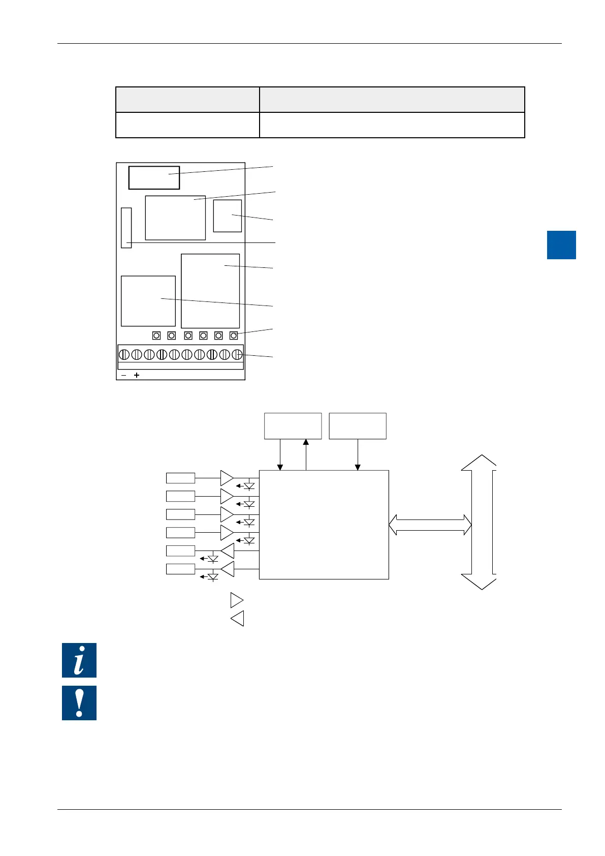
LEDs and connection terminals
9 8 7 6 5 4 3 2 1 0
A0
A1 E3 E2 E1 E0
Bus connector
FPGA
PROM on socket
Oscillator
Input filter
Output transistors
LEDs
Screw terminals
Block diagram
E 0
E 1
E 2
E 3
A 0
A 1
User PROM Oscillator
PCD Bus
Input filter and adapter 24V to 5V
Output amplifier 5 .to. 32 V
DC
(Uext)
Input "A"
Input "B"
EnableC
EnableM
For further details, please refer to manual 26/755 "PCD2.H110 - Universal count-
ing and measuring module".
Watchdog: This module cannot be used on the base address 240 (or 496 for the
PCD2.M17x), because it would interact with the watchdog, and would cause a
malfunction. For details, please refer to the section A4 “Hardware Watchdog”,
which describes the correct use of the watchdog in conjunction with PCD
components.
LED 0 State of input “A”
LED 1 State of input “B”
LED 2 State of input “EnableC”
LED 3 State of input “EnableM”
LED 4 State of output “CCO”