Saia-Burgess Controls AG
Manual I/O-modules for PCD1 │ PCD2 series │ Document 27-600 – Release ENG09 │ 2019-05-01
5-119
I/O modules PCD1|PCD2
PCD2.H150
5
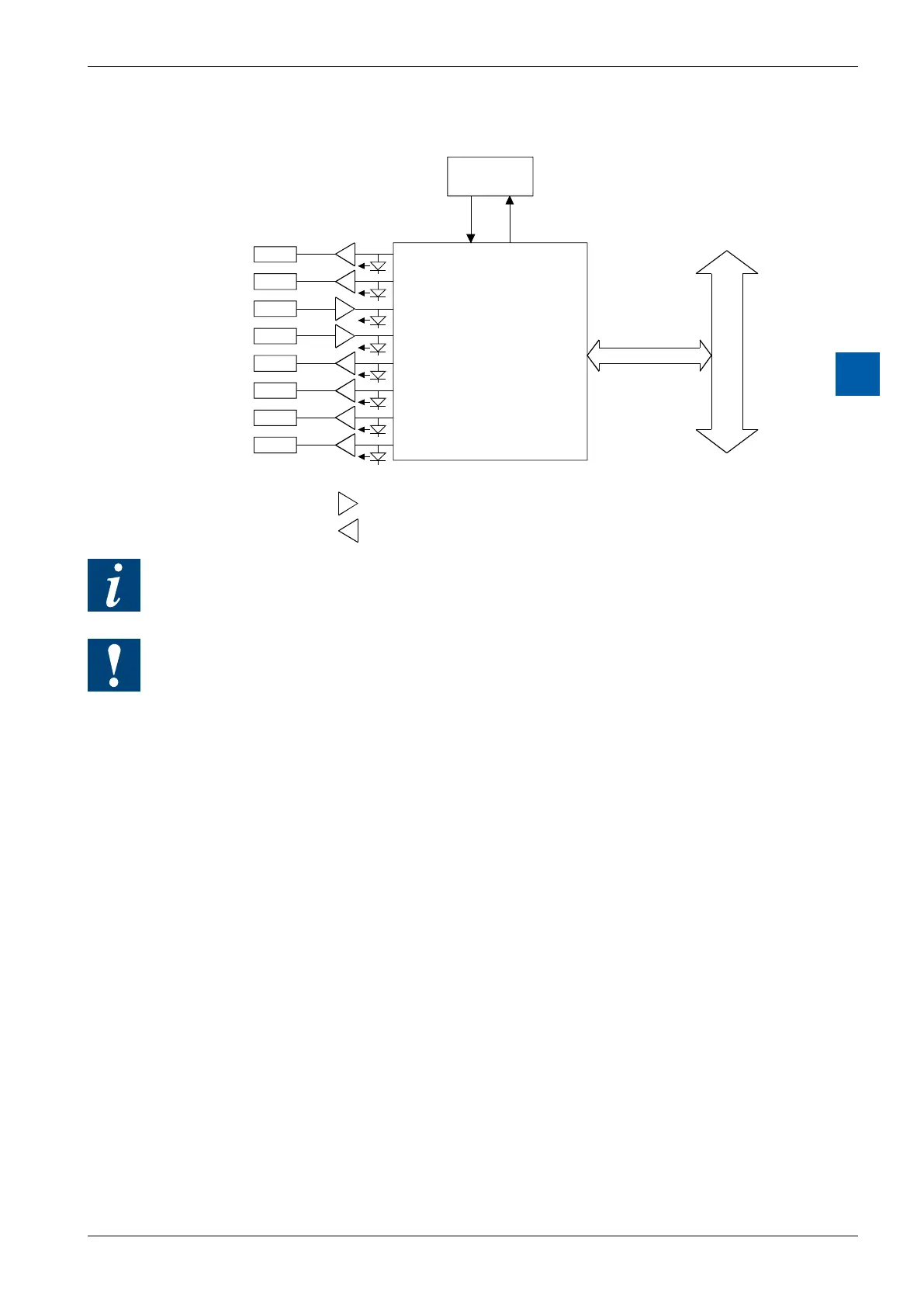
Block diagram
User PROM
Input filter and adaptation 24V to 5V
Output amplifier 5 .to. 32 V
DC (Uext)
For further details, please refer to manual 26/761 “PCD2.H150 - SSI interface for
absolute encoder”.
Watchdog: This module cannot be used on the base address 240 (or 496 for the
PCD2.M17x), because it would interact with the watchdog, and would cause a
malfunction.
For details, please refer to the section A4 “Hardware Watchdog”, which describes
the correct use of the watchdog in conjunction with PCD components.