Saia-Burgess Controls AG
Manual I/O-modules for PCD1 │ PCD2 series │ Document 27-600 – Release ENG09 │ 2019-05-01
6-4
I/O modules PCD3
Introduction to I/O modules
6
Type
I/Os
Description
I/O
connector type ³
Page
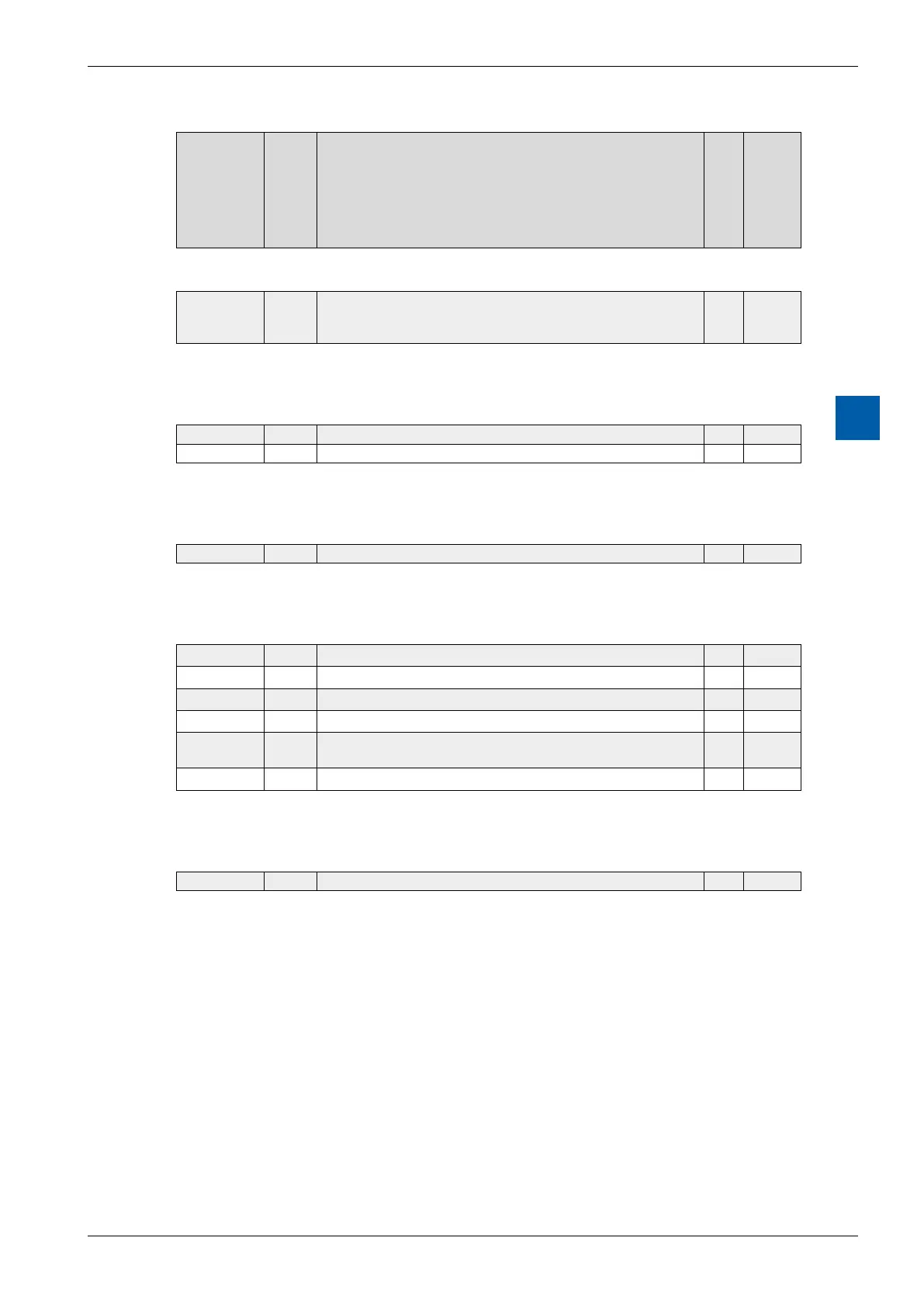
Analogue output module for manual operation
PCD3.W800 4 O Manual control module
3 outputs 0…10 V with manual control, 1 output 0…10 V
without
J 6-105
Weighing modules
PCD3.W710 1 I 1 weighing systems, up to 6 weighing cells 18 bit ²) E 6-109
PCD3.W720 2 I 2 weighing systems, up to 6 weighing cells 18 bit ²) E 6-109
Universal temperature measurement module
PCD3.W745 4 I Thermocouple module for J, K…thermocouples
8
) 6-110
Counting and motion control modules
PCD3.H100 Counter module up to 20 kHz A / B 6-112
PCD3.H110 Counter module up to 100 kHz A / B 6-117
PCD3.H150 SSI interface module A / B 6-119
PCD3.H210 Motion control module for stepper motors ²) A / B 6-122
PCD3.H310 Motion control module for servo-motors 1-axis encoder 24
VDC ²)
A / B 6-125
PCD3.H311 same as H310, with 1-axis encoder 5 VDC ²),
9
) A / B 6-125
Input/output simulator unit
PCD3.S100 Input/output simulator for PCD3.M/C/T - 6-129
²) These I/O modules cannot currently be used with the PCD3 RIO head station
³) I/O connectors are not provided with the I/O modules and must be ordered separately
4
) Current consumption from internal 5 V bus, capacity max. 600 mA for the PCD3.Mxxx0,
max. 650 mA for the PCD3.T76x and max. 1000 mA for the PCD3.C200
5
) Current consumption from internal 24 V bus, capacity max. 100 mA for the PCD3.Mxxx0, for the
PCD3.T76x and for the PCD3.C200
6
) On request
7
Pluggable system cable with connector on Saia PCD
®
to connect via 34-pole ribbon connector:
The
preconguredcableswithconnectorsonthePCDallowmanyI/Opointstobeconnectedquicklyand
easily. The system cables are described in the PCD1/2 manual,
Document-no 26/737.
8
) Non-pluggable cage clamp terminals
9
) Up to max.300 mA for the encoder, this current also loads the +5 V bus on the module