Saia-Burgess Controls AG
Manual I/O-modules for PCD1 │ PCD2 series │ Document 27-600 – Release ENG09 │ 2019-05-01
6-15
I/O modules PCD3
PCD3.E16x
6
The following materials can be ordered from ‘3M’:
●Socket connector 34-pole Type 3414-6600
●(Metalstrainrelief)*) Type3448-2034
●(Handleforsocketconnector34-pole)*) Type3490-3
Matching cables can be ordered in reels from '3M':
●Ribbon cable 34-pole,
greywithpin1identication Type3770/34or3801/34
●Round cable 34-pole,
greywithpin1identication Type3759/34
*)optional
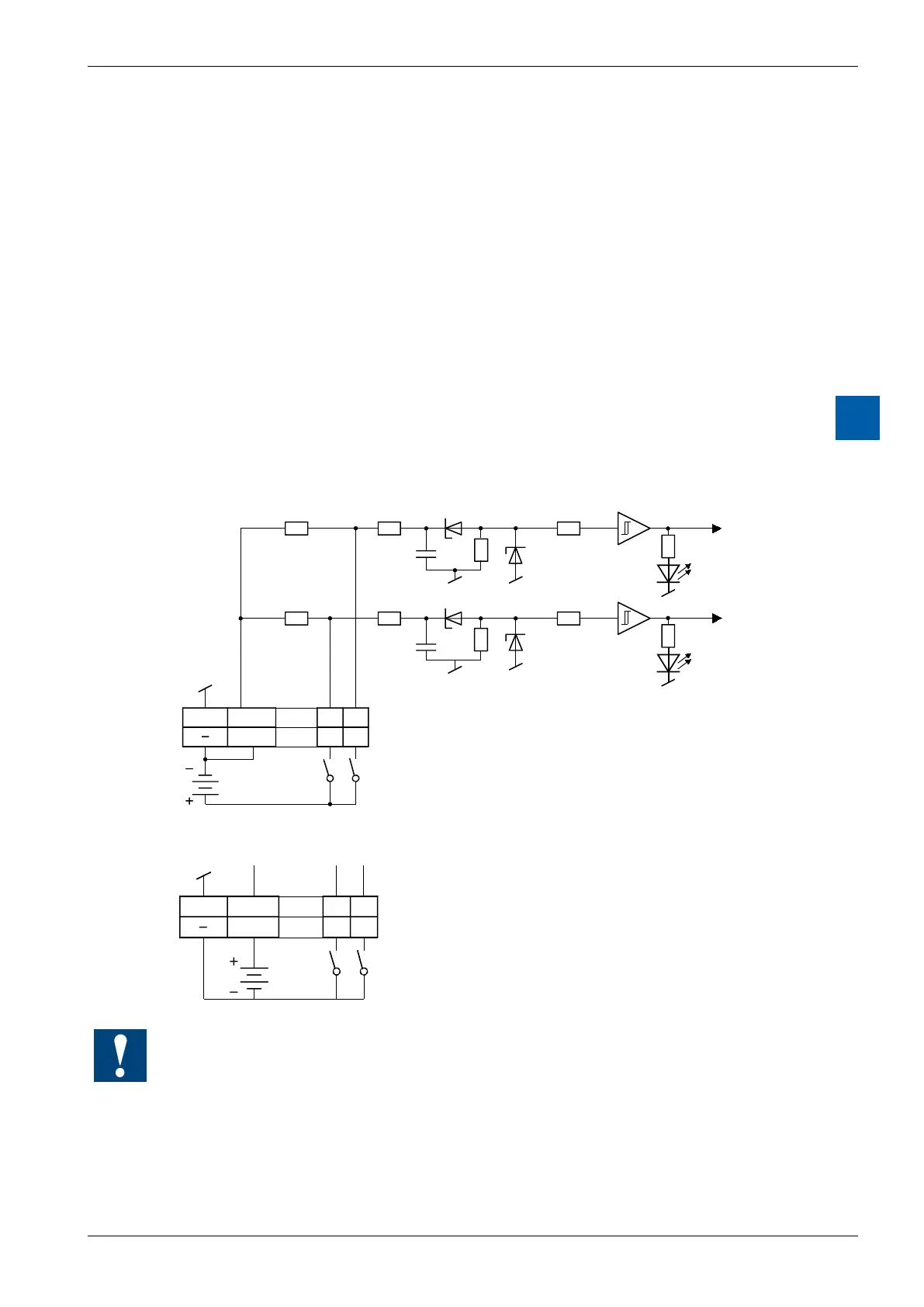
Input circuits and terminal designation
Depending on external wiring, this module may be used for source or sink opera-
tion.
Source operation (positive logic):
1, 3, 5, 7
17, 19, 21, 23
9, 11, 13, 15
25, 27, 29, 31
L E1 E0
30 32
10k 10k
10k 10k
Ue 24 VDC
Ribbon cable connector
Switch closed: (+ at input): signal state "H", LED lights up
Schalter open: signal state "L", LED off
LED
LED
Sink operation (negative logic):
1, 3, 5, 7
17, 19, 21, 23
9, 11, 13, 15
25, 27, 29, 31
L E1 E0
30 32
Ribbon cable connector
Switch closed: (- at input): signal state "L", LED off
Switch open: signal state "H", LED lights up
Ue = 24 VDC
Watchdog: This module can interact with the watchdog, if it is used on base address 240. In
this case, the last input with address 255 cannot be used.
For details, please refer to the section A4 “Hardware Watchdog”, which describes the correct
use of the watchdog in conjunction with PCD components.