Saia-Burgess Controls AG
Manual I/O-modules for PCD1 │ PCD2 series │ Document 27-600 – Release ENG09 │ 2019-05-01
6-27
I/O modules PCD3
PCD3.A400
6
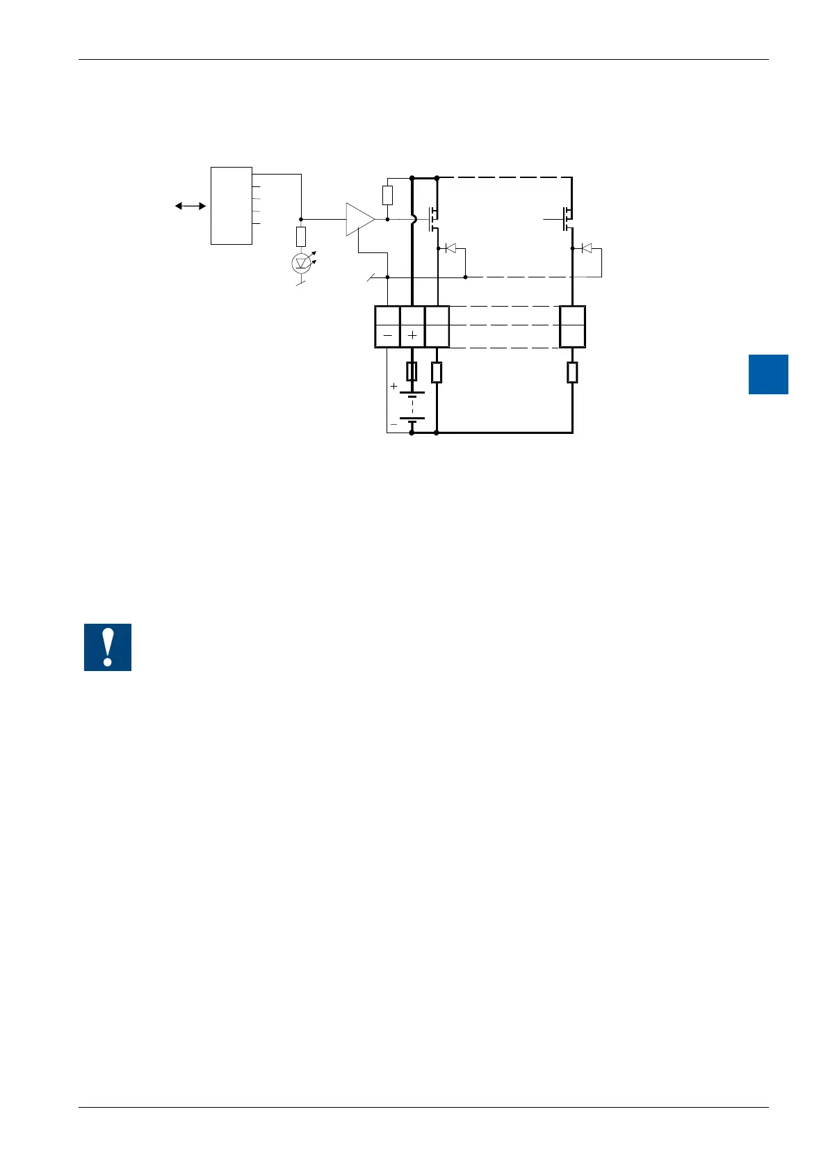
Output circuits and terminal designation
A0
089 7
I/O Bus
PCD Bus
24 VDC
Fuse
A7
Output
transistors
Protective
diodes
Terminals
Loads
LED-
address A7
Output conducting (set): LED on
Outputdisconnected(reset): LEDo
Fuse: It is recommended that each module should be separately pro-
tected
with a fast-blow (S) 4 A fuse.
Watchdog:Thismodulecanbeusedonallbaseaddresses;thereisnointeractionwiththe
watchdog on the CPUs.
For details, please refer to the section A4 “Hardware Watchdog”, which describes the correct
use of the watchdog in conjunction with PCD components.