Saia-Burgess Controls AG
Manual I/O-modules for PCD1 │ PCD2 series │ Document 27-600 – Release ENG09 │ 2019-05-01
6-34
I/O modules PCD3
PCD3.A200
6
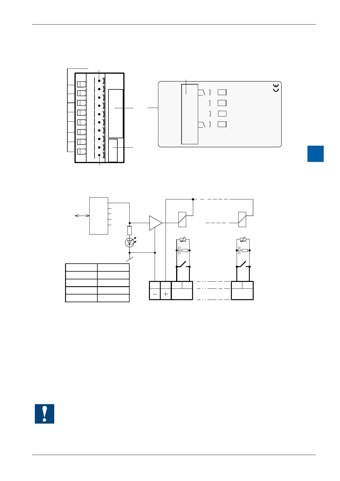
LEDs and connection terminals
+
–
–
–
–
–
0
1
2
3
4
5
6
7
PCD3.A200
A
2
0
0
0
1
2
3
4
5
6
7
8
9
A0
A1
A2
A3
LED 0...7
Terminal 0
Description
Label
Address
Label
Terminal
4 Rel. Outputs 2A250VAC
24VDC
Output circuits and terminal designation
A0
0189
A3
67
I/O Bus
PCD Bus
Contact
protection
Relay
contacts
Terminals
24 VDC Isolated contacts
Adress
LED A3
VDR = 250 VAC/400 A
R = 33 Ohm
C = 10 nF
LED Output
0 O0
1 O1
2 O2
3 O3
Relay energized (contact closed): LED on
Relayreset(contactopen): LEDo
24 VDC must be connected to the +/- terminals.
With an open relay contact, the current leakage through the contact protection is
0.7 mA (at 230 V / 50 Hz). This should be taken into account for smaller AC loads.
If this is too high, it is recommended to use a PCD3.A220 module (without contact
protection).
Watchdog:Thismodulecanbeusedonallbaseaddresses;
there is no interaction with the watchdog on the CPUs.