Saia-Burgess Controls AG
Manual I/O-modules for PCD1 │ PCD2 series │ Document 27-600 – Release ENG09 │ 2019-05-01
6-38
I/O modules PCD3
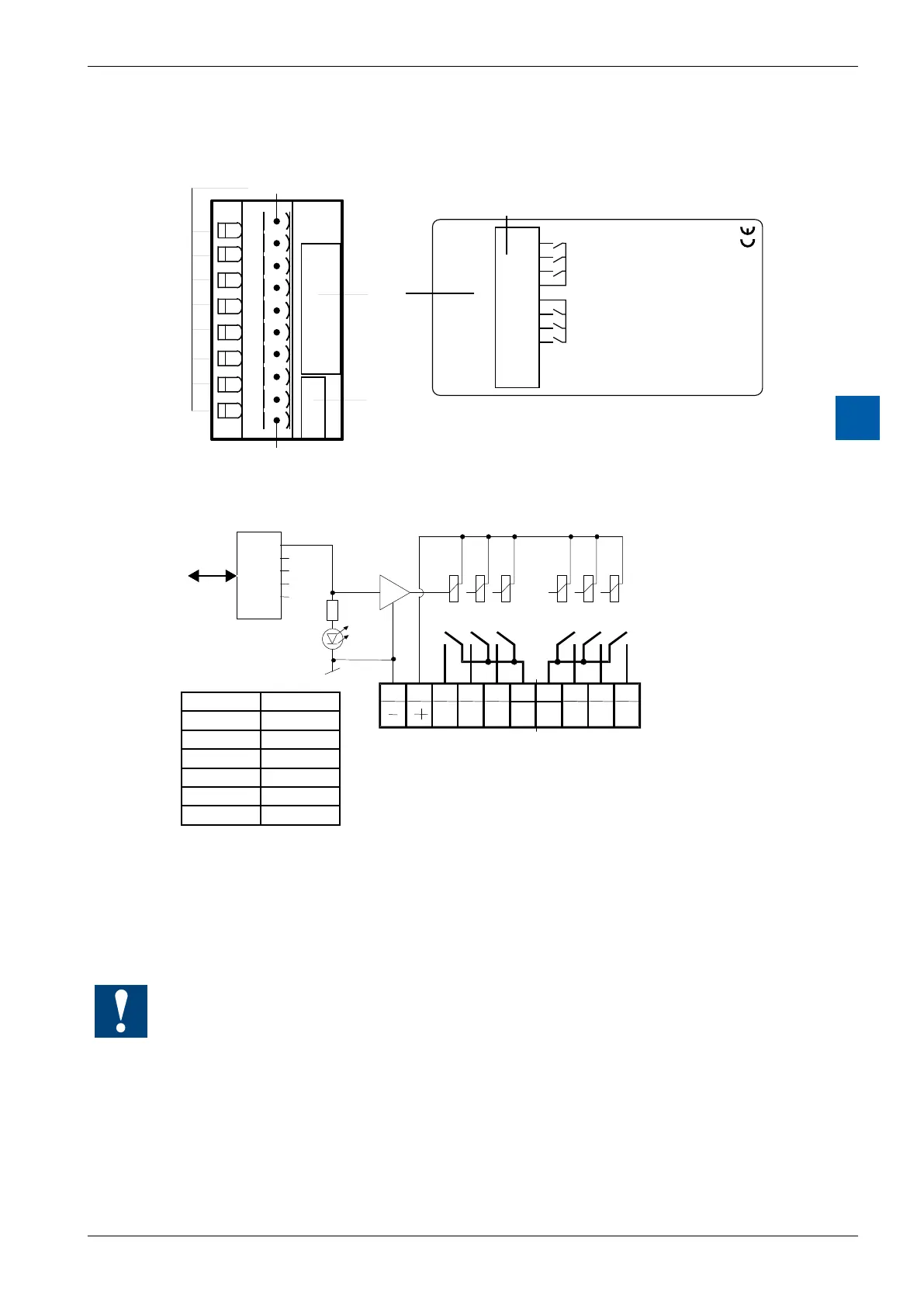
PCD3.A220
6
LEDs and connection terminals
0
1
2
3
4
5
6
7
LED 0...7 Terminal 0
Description
Label
Address
Label
PCD3.A220
6 Rel. Outputs 2A
/250VAC
0
1
2
3
4
5
6
7
8
9
A0
A1
A2
C
C
A3
A4
A5
+
–
24VDC
Terminal 9
Terminal
A
2
2
0
Output circuits and terminal designation
LED Output
0 O0
1 O1
2 O2
3 O3
4 O4
5 O5
one common terminal
Relay energized (contact closed): LED on
Relayreset(contactopen): LEDo
24 VDC must be connected to the +/- terminals.
Watchdog:Thismodulecanbeusedonallbaseaddresses;
there is no interaction with the watchdog on the CPUs.