Saia-Burgess Controls AG
Manual I/O-modules for PCD1 │ PCD2 series │ Document 27-600 – Release ENG09 │ 2019-05-01
6-40
I/O modules PCD3
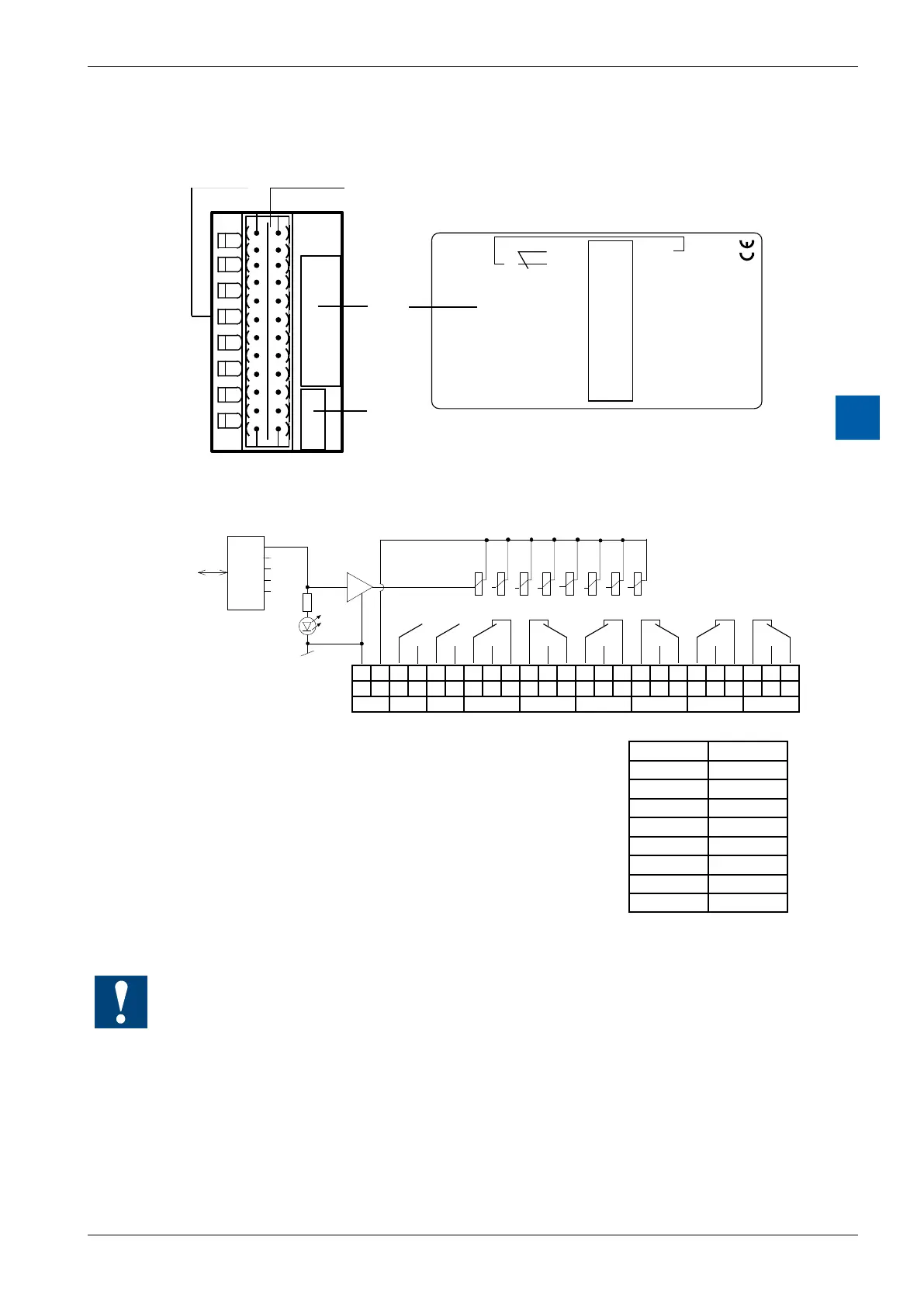
PCD3.A251
6
LEDs and connection terminals
LED 0...7 Terminals
Description
Label
Address
Label
PCD3.A251
8 Rel. Outputs 2A
/24VDC
1
3
5
7
9
11
13
15
17
19
21
23
0
2
4
6
8
10
12
14
16
18
20
22
A0
A0
A1
A2
A2
A3
A4
A4
A5
A6
A7
+
co
nc
no
co
nc
no
co
nc
no
co
co
no
nc
co
no
nc
co
no
nc
co
no
no
A0
A1
A1
A2
A3
A3
A4
A5
A5
A6
A7
–
0 1
22 23
0
1
2
3
4
5
6
7
A
2
5
1
Output circuits and terminal designation
23 22 21 20 19 18 17 16 15 14 13 12 11 10 9 8 7 6 5 4 3 2 1 0
- + co no co no co no nc nc no co co no nc nc no co co no nc nc no co
24 VDC
A7 A6 A5 A4 A3 A2 A1 A0
Terminals
Relay contacts
Relay energized (contact closed): LED on
Relayreset(contactopen): LEDo
24 VDC must be connected to the +/- terminals.
LED Outputs
0 O0
1 O1
2 O2
3 O3
4 O4
5 O5
6 O6
7 O7
Watchdog:Thismodulecanbeusedonallbaseaddresses;
there is no interaction with the watchdog on the CPUs.