Saia-Burgess Controls AG
Manual I/O-modules for PCD1 │ PCD2 series │ Document 27-600 – Release ENG09 │ 2019-05-01
6-42
I/O modules PCD3
PCD3.A410
6
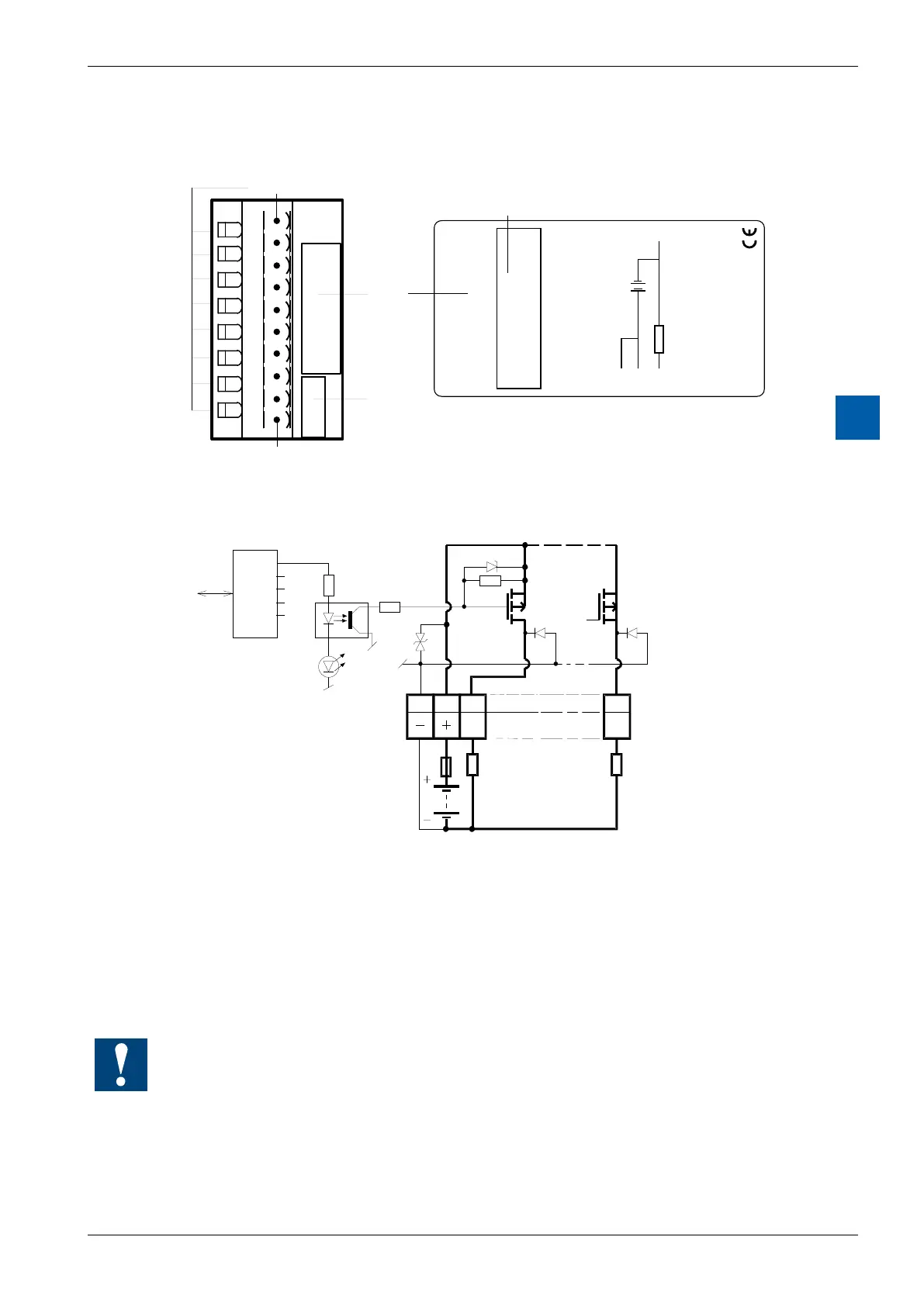
LEDs and connection terminals
0
1
2
3
4
5
6
7
LED 0...7 Terminal 0
Description
Label
Address
Label
24VDC
PCD3.A410
8 Tr. Outputs 0.5A
/24VDC
A0
A1
A2
A3
A4
A5
A6
A7
+
–
–
+
+
A
n
24V
+ –
0
1
2
3
4
5
6
7
8
9
Terminal 9
Terminal
A
4
1
0
Output circuits and terminal designation
Output
transistors
(MOSFET)
Protective
diodes
Output conducting (set): LED on
Outputdisconnected(reset): LEDo
Fuse: It is recommended that each module should be separately pro-
tected
with a fast-blow (S) 4 A fuse.
Watchdog:Thismodulecanbeusedonallbaseaddresses;
there is no interaction with the watchdog on the CPUs.