Saia-Burgess Controls AG
Manual I/O-modules for PCD1 │ PCD2 series │ Document 27-600 – Release ENG09 │ 2019-05-01
6-49
I/O modules PCD3
PCD3.A860
6
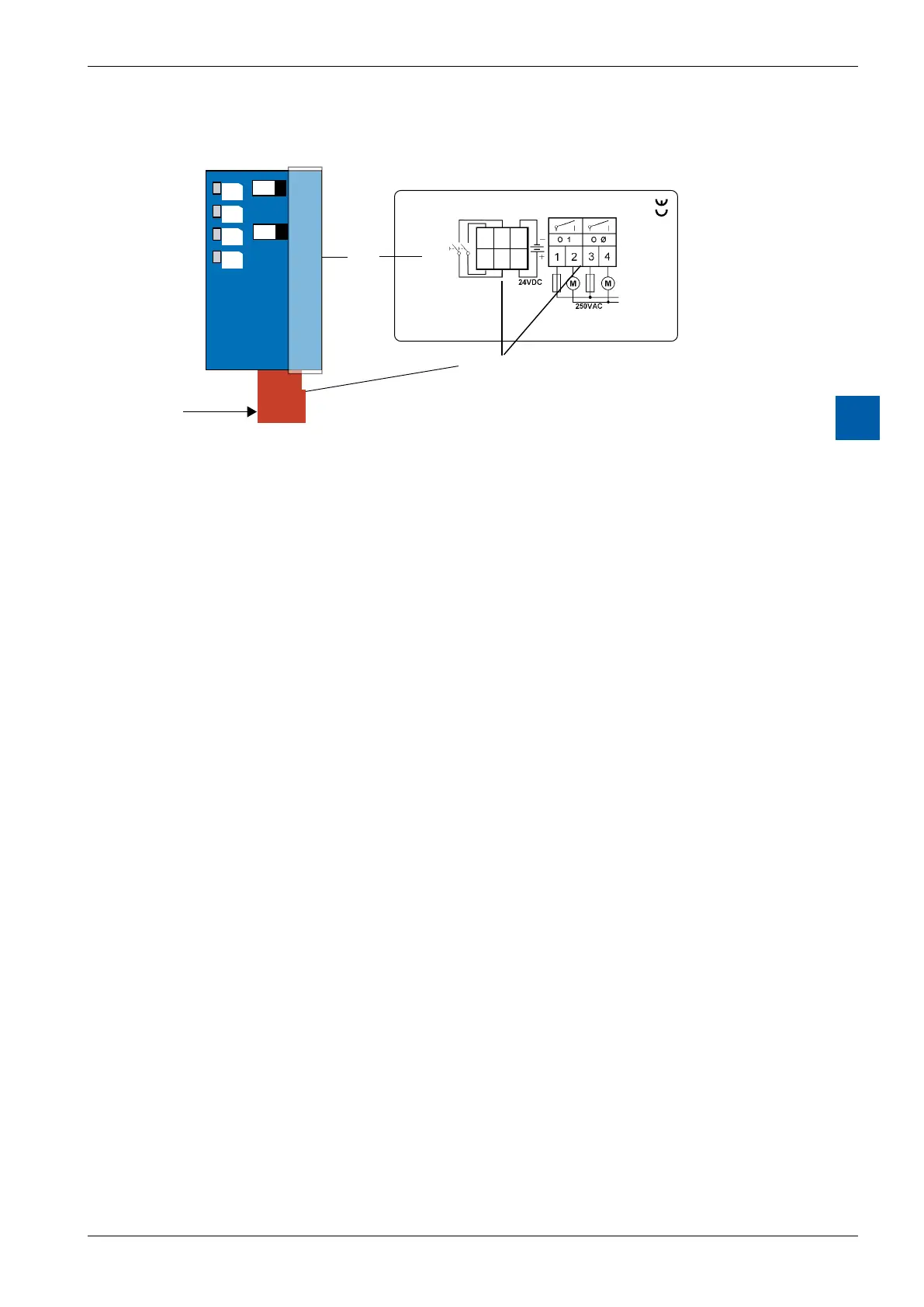
LEDs and connection terminals
1 A
1 A
I Ø
O Ø
O 1
I 1
6 4
2
5 3
1
PCD3.A860
2 inp./2 out. 12A 250 VAC
A
8
6
0
Description-
label
Pin 1 in front
Terminals
Control elements
● Impulseswitch:
The switches can be used to activate the two inputs manually.
Thekeyshavethesameeectastheexternalinputs.
A=Restposition;themoduleworksviatheinputsandviathe
FBox for the relevant function.
1 = Switch on manually (impulse only)
● LEDs:
The LEDs (red) display the state of the inputs/outputs.
I Ø + I 1 are also used to display the U
ext
error. If U
ext
is not connected, the two
inputLEDsashtogether.
I (Ø+1): Inputs 0 + 1 + U
ext
error
O (Ø+1): Outputs 0 + 1
● Four-poleconnector:
O Ø Skylight 0 / blind motor up
O 1 Skylight 1 / blind motor down
● Six-poleconnector:
I Ø (pin 5) – GND (pin 6) external switch for Input 0
(skylight 0 / blind motor up)
I 1 (pin3) – GND (pin4) external switch for Input 1
(skylight 1 / blind motor down)
Uext (pin 1) – GND (pin 2) external supply + 24 VDC
TheGNDconnectionsarettedtothecircuitboard.