Saia-Burgess Controls AG
Manual I/O-modules for PCD1 │ PCD2 series │ Document 27-600 – Release ENG09 │ 2019-05-01
6-63
I/O modules PCD3
PCD3.W2x0
6
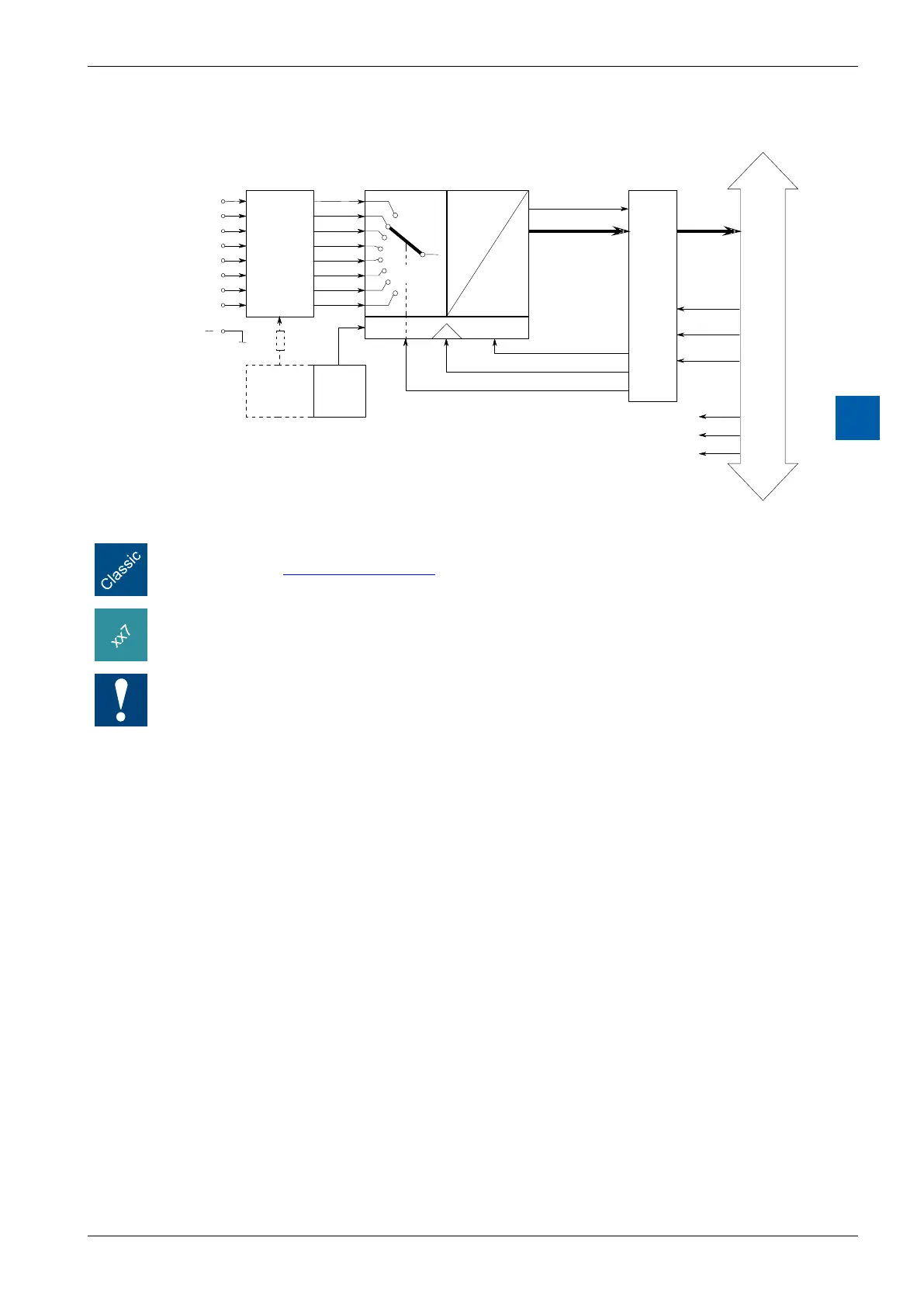
Block diagram
Programming
Programming examples for the PCD3.W2x0 can be found in a separate manual and on the
TCS Support site www.sbc-support.com.
xx7andRIOs:thermwarereadsinthevaluesaccordingtotheconguration(I/OBuilderor
networkcongurator).
Watchdog: This module can interact with the watchdog, if it is used on base address 240. In
this case, the last input with address 255 cannot be used.
For details, please refer to the section A4 “Hardware Watchdog”, which describes the correct
use of the watchdog in conjunction with PCD components.