Saia-Burgess Controls AG
Manual I/O-modules for PCD1 │ PCD2 series │ Document 27-600 – Release ENG09 │ 2019-05-01
5-12
I/O modules PCD1|PCD2
PCD2.E110, PCD2.E111, PCD2.E112 and PCD2.E116
5
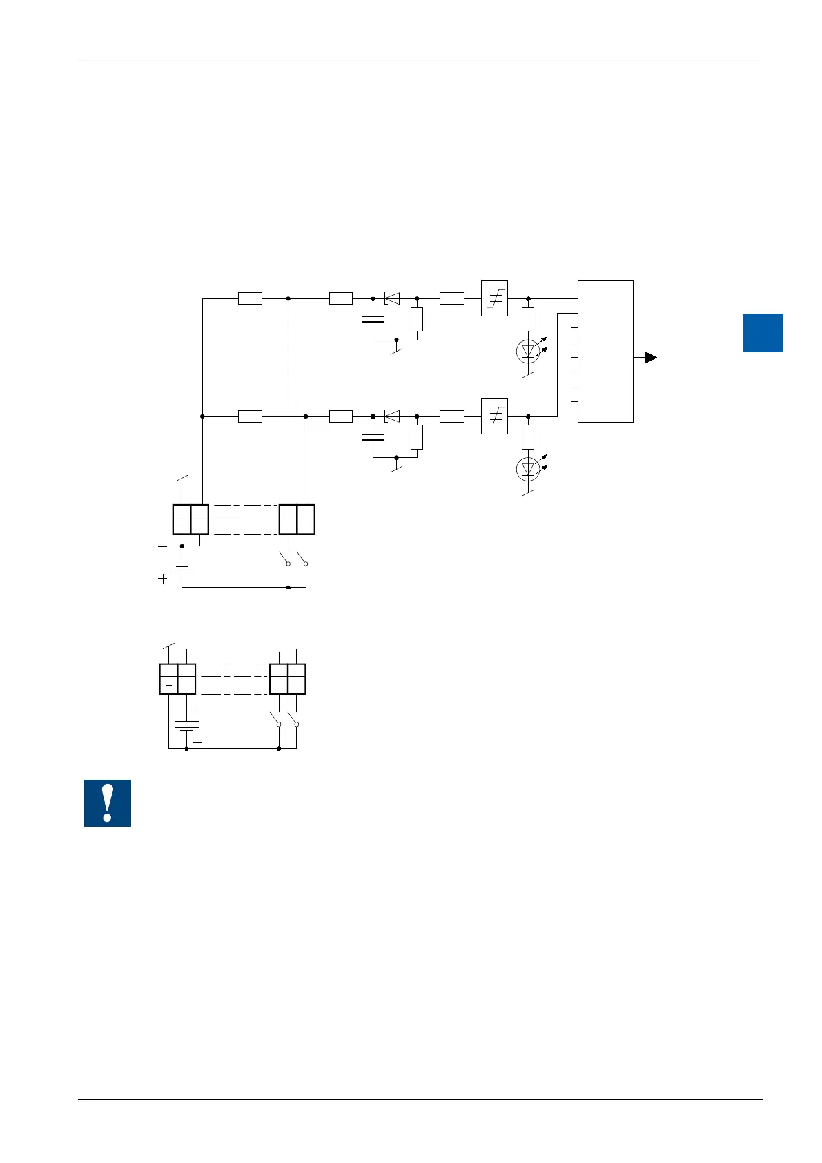
Input circuits and terminal designation
Depending on external wiring, this module may be used for source or sink opera-
tion.
Source operation (positive logic):
E1
4k7
4k7
10k
10k
E0
01
L
89
E0E1
I/O
Bus
Inter-
face
PCD Bus
Ue : 24 V
DC
12 V
DC
5 V
DC
Load resistors
Input filter
Threshold
switch
LED
Switch closed
(positive at input) : Input state "H" = LED on
Switch open : Input state "L" = LED off
Sink operation (negative logic):
E0
0
E1
1
L
89
Switch closed
(negative at input) : Input state "L" = LED off
Switch open : Input state "H" = LED on
Ue : 24 V
DC
12 V
DC
5 V
DC
Watchdog:Thismodulecanbeusedonallbaseaddresses;thereisnointeraction
with the watchdog on the CPUs. For details, please refer to the section A4 “Hard-
ware Watchdog”, which describes the correct use of the watchdog in conjunction
with PCD components.