Saia-Burgess Controls AG
Manual I/O-modules for PCD1 │ PCD2 series │ Document 27-600 – Release ENG09 │ 2019-05-01
6-81
I/O modules PCD3
PCD3.W4x0
6
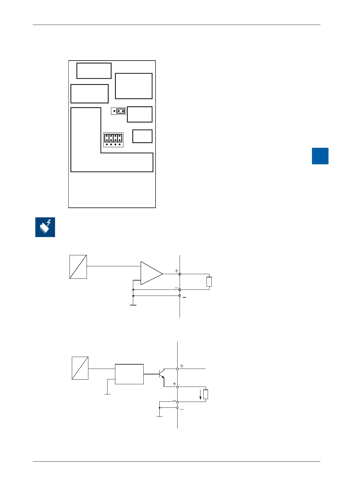
Layout (housing open, for instructions, see section 6.1.5)
23 1 0
V
C
4 0
OsetjumperJ1(PCD3.W410only)
Position “0”: 0… 10 V or 0… 20 mA
Position “4”: 2… 10 V or 4… 20 mA
Jumper J2 for current/voltage
(PCD3.W410 only)
Position “V”: Voltage output
Position “C”: Current output
Factory settings (PCD3.W410):
● Position “V”: Voltage output
● Position “0”: range 0…10 V:
Changing the jumpers
On this circuit board there are components that are sensitive to electrostatic discharges. For
further information, refer to Appendix A1, "Icons"
Connection for 0…10 V
4 (A2)
D
A
5
U
R
≥
3 k
Ω
Connection for 0…20 mA or 4…20 mA
(selectable with jumpers on type PCD3.W410)
4 (A2)
5
I
R = 0...500 Ω
D
A
VOLTAGE
CONTROLLED
CURRENT
SOURCE
+ 24 VDC
An external 24 VDC sup-
ply is required for current
outputs.