Saia-Burgess Controls AG
Manual I/O-modules for PCD1 │ PCD2 series │ Document 27-600 – Release ENG09 │ 2019-05-01
6-90
I/O modules PCD3
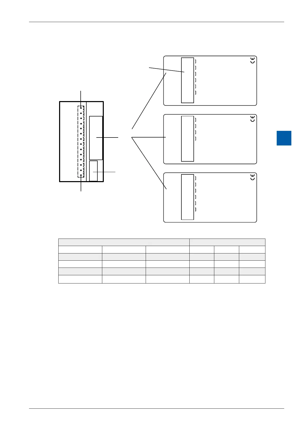
PCD3.W6x5
6
Connections
0
1
2
3
4
5
6
7
8
9
10
11
12
13
A0
–
A1
–
A2
–
A3
–
A4
A5
–
–
5 A26W.3DCP
6
ts -10 V...+10 V
uptuo
W
6
2
5
Galvanic Separated
5 A16W.3DCP
4 ts 0...20 mAuptuo
Galvanic Separated
A0
–
A1
–
A2
–
A3
–
+
–
24VDC
0
1
2
3
4
5
6
7
8
9
10
11
12
13
W
6
1
5
5 A06W.3DCP
6 ts 0...10 Vuptuo
Galvanic Separated
A0
–
A1
–
A2
–
A3
–
A4
A5
–
–
0
1
2
3
4
5
6
7
8
9
10
11
12
13
W
6
0
5
Terminals
Terminal 0
Description-
label
Address-
label
Terminal 13
Digital/analogue values
Output signals and type Digital values
PCD3.W605 PCD3.W615 PCD3.W625 Classic xx7 Simatic
+ 10.0 V + 20 mA +10 V 1023 1023 27684
+ 5.0 V + 10 mA 0 V 512 512 13842
+ 4 mA 205 205 5530
0 V 0 mA –10 V 0 0 0
Notes on the output range
BalancingtheosetandtheamplicationisdoneforthePCD3.W6x5digitallyby
the µC. As there is no potentiometer, the output range has been slightly enlarged
to cover maximum values even in the worst case.
Typical output range (without component tolerances):
PCD3.W605: – 0.26 V…+ 10.36 V (instead of 0…+ 10 V)
PCD3.W615: 0 mA …21.4 mA (instead of 0…20 mA)
PCD3.W625: – 10.62 V … 10.36 V (instead of – 10…+10 V)
This range is broken down on a 10 bit scale (1024 steps), as before. The result is
the following LSB resolution:
PCD3.W605: 1 LSB = 10.38 µV
PCD3.W615: 1 LSB = 21.7 µA
PCD3.W625: 1 LSB = 20.75 µV