Saia-Burgess Controls AG
Manual I/O-modules for PCD1 │ PCD2 series │ Document 27-600 – Release ENG09 │ 2019-05-01
6-106
I/O modules PCD3
PCD3.W800
6
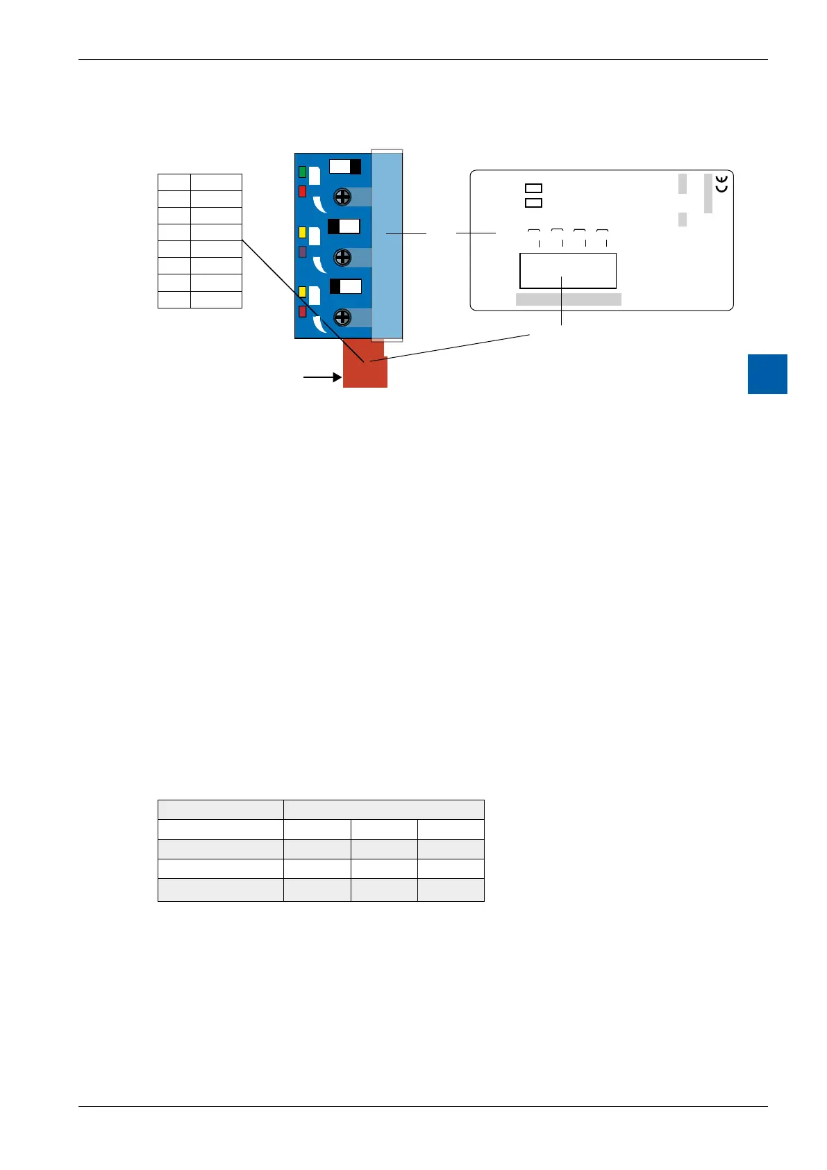
LEDs and connection terminals
M A
M A
GND
A0
7
6
5
A1
4
3
A2
2
1
A3
Pin 8 in front
PCD3.W800
4 outputs 0 - 10 V
W
8
0
0
8
7
6
5
4
3
A0
A1
A2
A3
2
1
LEDs
green: Automatic
yellow: Manual
red: Output Voltage
Description-
label
Terminals
GND
GND
GND
8
M A
0
1
2
Control elements
Channels A0…A2 each have a toggle switch with the two positions
Manual and Automatic.
Thereare2LEDsttedperchannel:
The upper LED is two-colour and displays the operating mode for the channel:
amber=Manual;green=Automatic
The brightness (red) of the lower LED displays the output voltage of the channel
(Manual and Automatic)
Example (above):
Output 0: Automatic LED 1 = green
Value (100 %) LED 2 = red (max.)
Output 1: Manual LED 1 = amber
Value (15 %) LED 2 = red (weak)
Output 2: Manual LED 1 = amber
Value (85%) LED 2 = red (strong)
Digital/analogue values
Output signals Digital values
Classic xx7 Simatic
+ 10.0 V 1023 1023 27684
+ 5.0 V 511 511 13824
0 V 0 0 0
Theuserisabletosetapplication-specicparameters.Itispossibleforexampleto
work directly in %. For this purpose, the appropriate parameters should be set to
0…1,000 in the FBox, corresponding to 0…100% in the HeaVAC library.