Saia-Burgess Controls AG
Manual I/O-modules for PCD1 │ PCD2 series │ Document 27-600 – Release ENG09 │ 2019-05-01
6-113
I/O modules PCD3
PCD3.H100
6
Count modes:
Selectable with jumper
Terminals:
Plug-in 10-pole spring terminal block (4 405 4954 0) or
pluggable 10-pole screw terminal block (4 405 4955 0),
both for wires up to 2.5 mm²
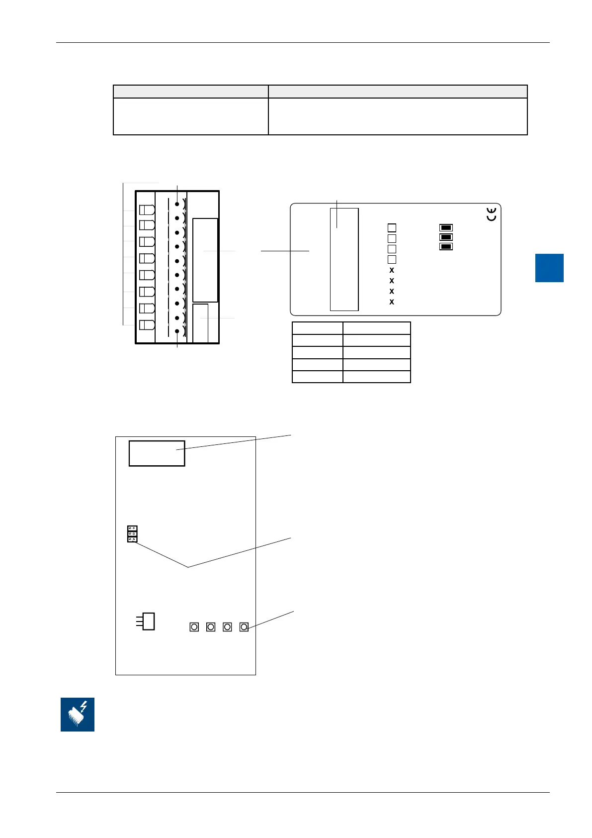
LEDs and connection terminals
0
1
2
3
4
5
6
7
LED 0...7
Terminal 0
Description
Label
Address
Label
A
–
B
–
CCO
–
+
–
PCD3.H100
2 Inputs 25 Khz
0
1
2
3
4
5
6
7
8
9
LEDs
En
A
B
CCO
Jumpers
SC
X1
X2
Terminal 9
Terminal
nc
nc
H
1
0
0
LED In- / Outputs
0 En
1 A
2 B
3 CCO
Layout (housing open, for instructions, see section 6.1.5)
CCO B A En
SC
x1
x2
Bus connector
Jumper for count modes
LEDs
“A” Input “A” 1
“B” Input “B” 2
“En” (Enable) Counter active 0
“CCO” Output “CCO” 3
Changing the jumpers
On this circuit board there are components that are sensitive to electrostatic discharges. For
further information, refer to Appendix A1, "Icons"