Saia-Burgess Controls AG
Manual I/O-modules for PCD1 │ PCD2 series │ Document 27-600 – Release ENG09 │ 2019-05-01
5-17
I/O modules PCD1|PCD2
PCD2.E165/166
5
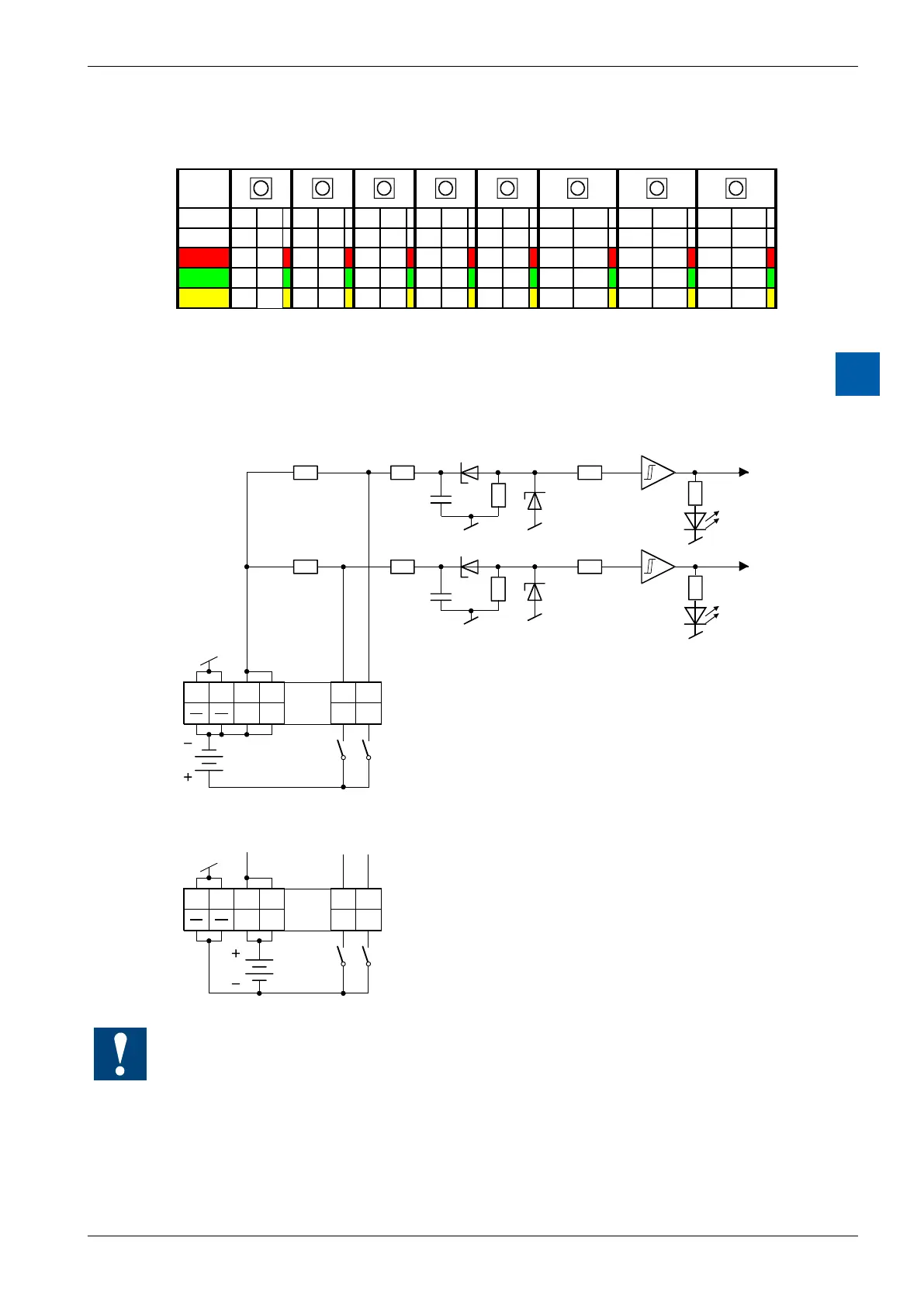
For every 2 inputs, a 3-colour LED is tted:
LED
is
E0 E1 E2 E3 E4 E5 E6 E7 E8 E9 E10 E11 E12 E13 E14 E15
o 0 0 0 0 0 0 0 0 0 0 0 0 0 0 0 0
red 1 0 1 0 1 0 1 0 1 0 1 0 1 0 1 0
green 0 1 0 1 0 1 0 1 0 1 0 1 0 1 0 1
yellow 1 1 1 1 1 1 1 1 1 1 1 1 1 1 1 1
Input circuits and terminal designation
Depending on external wiring, this module may be used for source or sink
operation.
Source operation (positive logic):
10 k 10 k
10 k 10 k
E1 E0L L
19 18 17 16 1 0
Ue 24 VDC
LED red
LED green
Screwless terminals
If both inputs 0 and 1 are
switched on, the yellow
(orange) LED lights up
Switch closed (+ at input): signal state "H", LED lights up
Switch open: signal state "L", LED off
Sink operation (negative logic):
E1 E0L L
19 18 17 16 1 0
Switch closed (- at input): signal state "L", LED off
Switch open: signal state "H", LED lights up
Screwless terminals
Ue 24 VDC
Watchdog:Thismodulecaninteractwiththewatchdog;ifitisusedonbase
address 240 (or 496 for the PCD2.M17x), the last input with address 255 (or 511
for the PCD2.M17x) cannot be used.
For details, please refer to the section A4 “Hardware Watchdog”, which describes
the correct use of the watchdog in conjunction with PCD components.