Saia-Burgess Controls AG
Manual I/O-modules for PCD1 │ PCD2 series │ Document 27-600 – Release ENG09 │ 2019-05-01
6-118
I/O modules PCD3
PCD3.H110
6
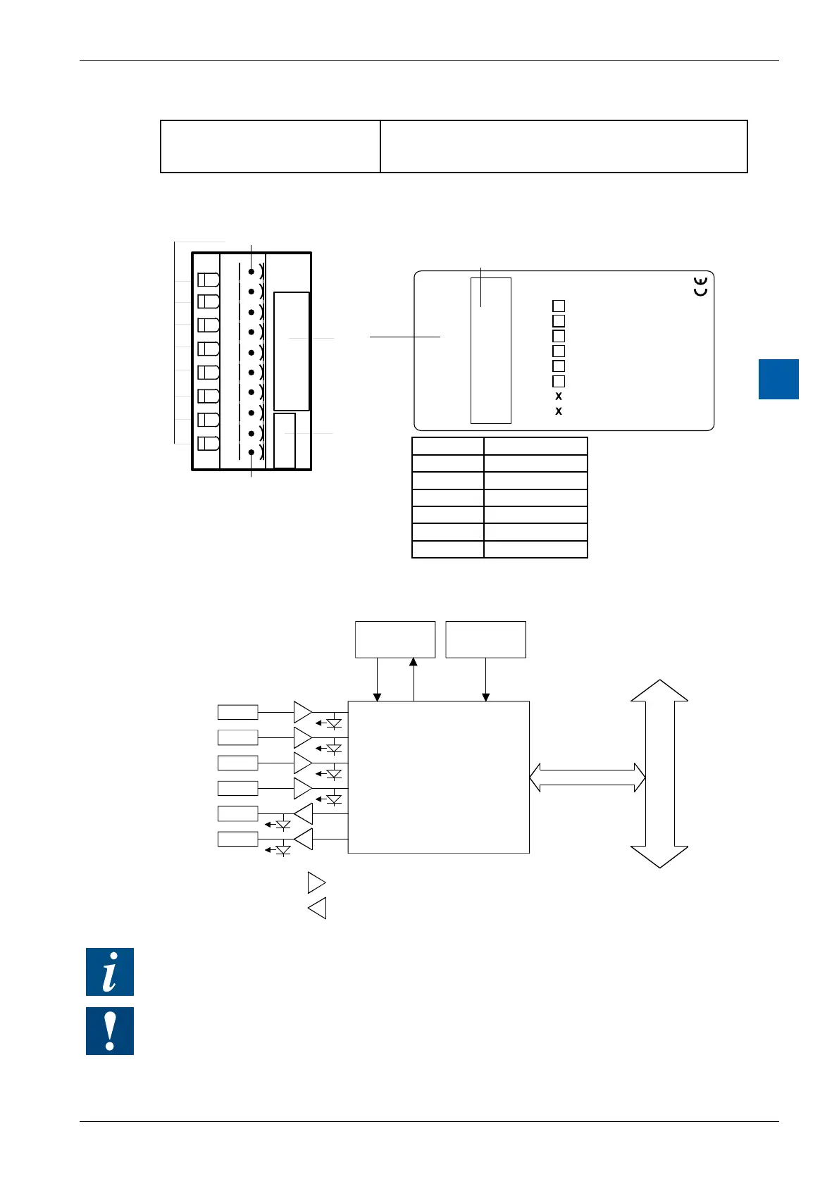
Terminals:
Plug-in 10-pole spring terminal block (4 405 4954 0) or
pluggable 10-pole screw terminal block (4 405 4955 0),
both for wires up to 2.5 mm²
LEDs and connection terminals
0
1
2
3
4
5
6
7
LED 0...7 Terminal 0
Description
Label
Address
Label
A
B
EnC
EnM
CCO
TCO
nc
nc
+
–
0
1
2
3
4
5
6
7
8
9
PCD3.H110
8 universalI
/Os
A
B
EnC
EnM
CCO
TCO
LEDs
Terminal 9
Terminal
H
1
1
0
LED In- / Outputs
0 A
1 B
2 EnC
3 EnM
4 CCO
5 TCO
Block diagram
1
Input filter and adapter 24V to 5V
Output amplifier 5 .to. 32 VDC (Uext)
For further details, please refer to manual 26/755 "PCD2.H110 - Universal counting and
measuring module".
Watchdog: This module can interact with the watchdog, if it is used on base address 240. In
this case, the last input with address 255 cannot be used.
For details, please refer to the section A4 “Hardware Watchdog”, which describes the correct
use of the watchdog in conjunction with PCD components.