Saia-Burgess Controls AG
Manual I/O-modules for PCD1 │ PCD2 series │ Document 27-600 – Release ENG09 │ 2019-05-01
5-37
I/O modules PCD1|PCD2
PCD2.A210
5
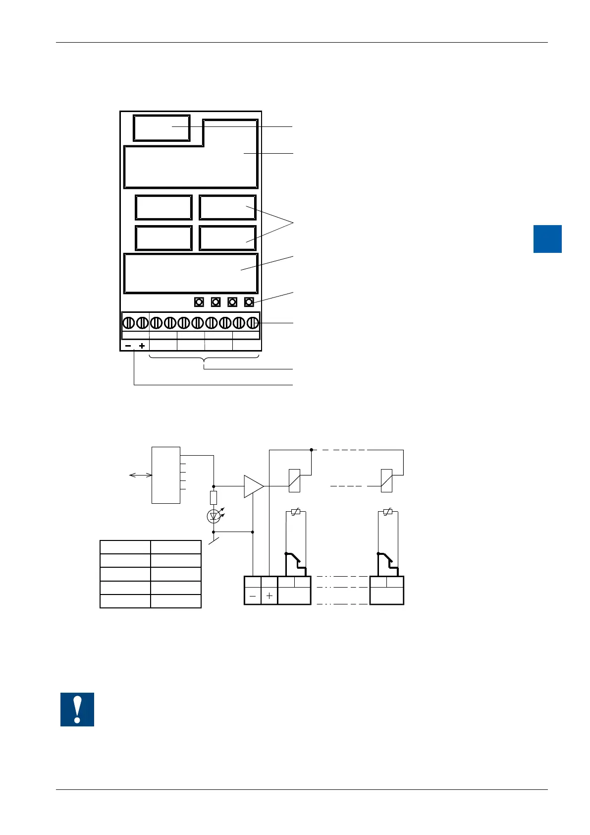
LEDs and connection terminals
9 8 7 6 5 4 3 2 1 0
A0A1A2A3
Bus
Bus interface
Relay
Contact protection
LED
Screw terminals
Relay contacts A0 to A3
Supply 24 V
DC
for Relay coils
Output circuits and terminal designation
A0
189
A3
67 0
I/O Bus
PCD Bus
Contact
protection
Relay
contacts
Terminals
24 VDC Isolated contacts
Address-
LED A3
Relay energized (contact open): LED on
Relayreset(contactclosed): LEDo
24 VDC must be connected to the +/- terminals.
Watchdog:Thismodulecanbeusedonallbaseaddresses;thereisnointerac-
tion with the watchdog on the CPUs. For details, please refer to the section A4
“Hardware Watchdog”, which describes the correct use of the watchdog in con-
junction with PCD components.
LED Output
0 A0
1 A1
2 A2
3 A3