Saia-Burgess Controls AG
Manual I/O-modules for PCD1 │ PCD2 series │ Document 27-600 – Release ENG09 │ 2019-05-01
5-39
I/O modules PCD1|PCD2
PCD2.A220
5
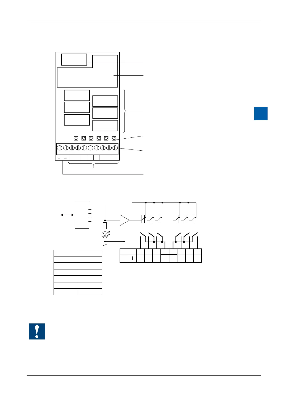
LEDs and connection terminals
9 8 7 6 5 4 3 2 1 0
A0A1A20-23-5A3A4A5
A0
A2
A1
A3
A5
A4
Bus connector
Bus interface
Relay
LEDs
Screw terminals
Supply 24 VDC for Relay coils
Relay contacts A0 to A5
Output circuits and terminal designation
89
A4
67
3-5
45
A1
2
3
A0
01
0-2 A2A3A5
I/O Bus
PCD Bus
Relay contacts
24 VDC
3 relay contacts have
one common terminal
Address
LED A5
Terminals
Relay energized (contact closed): LED on
Relayreset(contactopen): LEDo
24 VDC must be connected to the +/- terminals.
Watchdog:Thismodulecanbeusedonallbaseaddresses;thereisnointeraction
with the watchdog on the CPUs. For details, please refer to the section A4 “Hard-
ware Watchdog”, which describes the correct use of the watchdog in conjunction
with PCD components.
LED Output
0 O0 (A0)
1 O1 (A1)
2 O2 (A2)
3 O3 (A3)
4 O4 (A4)
5 O6 (A5)