Saia-Burgess Controls AG
Manual I/O-modules for PCD1 │ PCD2 series │ Document 27-600 – Release ENG09 │ 2019-05-01
5-43
I/O modules PCD1|PCD2
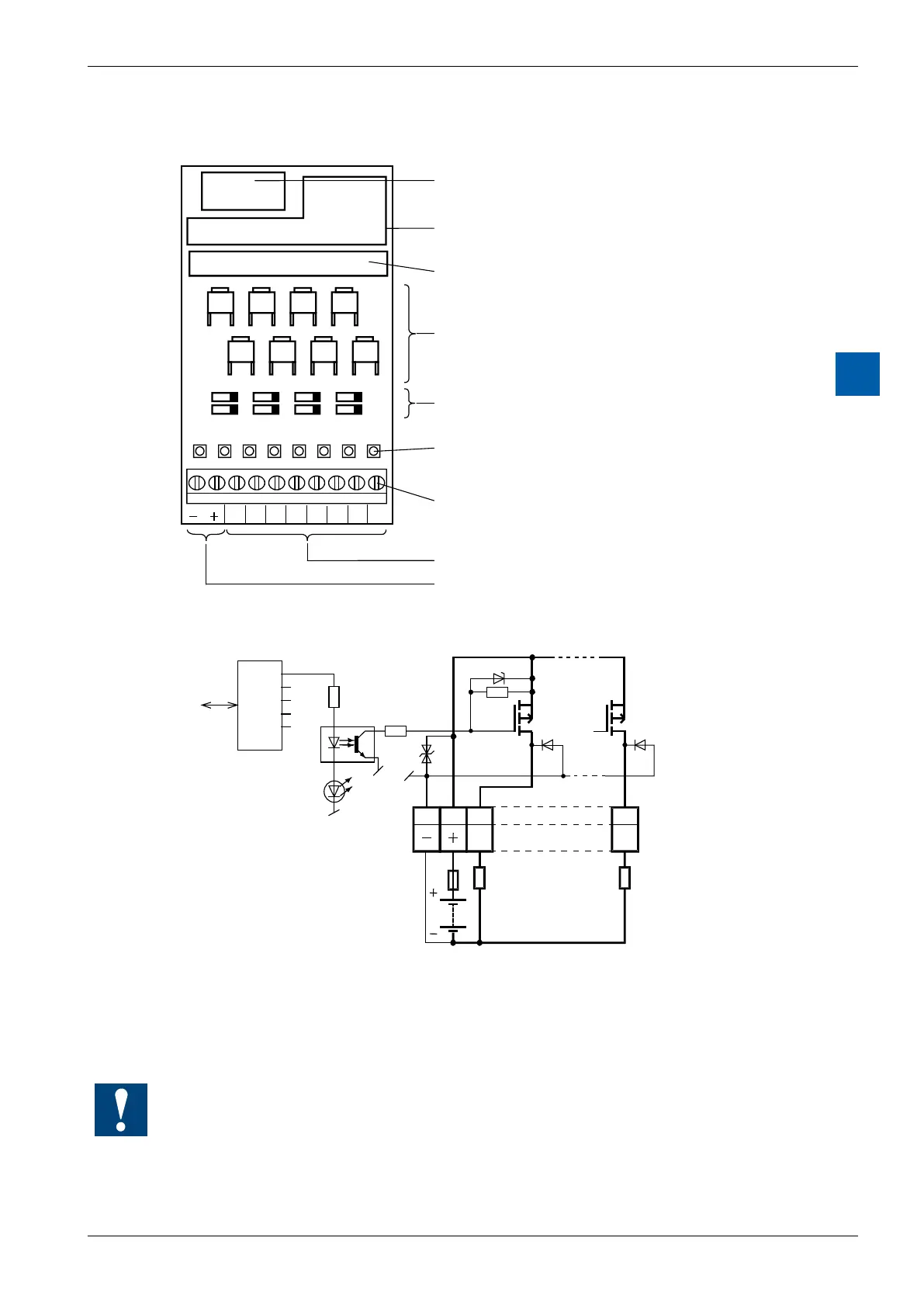
PCD2.A410
5
LEDs and connection terminals
9 8 7 6 5 4 3 2 1 0
A0A1A2A3A4A5
A5A3A1
A4A2A0 A6
A7
A6A7
Bus connector
Bus interface
Optocoupler
Output transistors (MOSFET)
Protective diodes
LEDs
Screw terminals
Outputs
Load supply 24 VDC
Output circuits and terminal designation
18V
Bus
PCD Bus
24 VDC
LED
adresse A7
Output
transistors
(MOSFET)
Protective
diodes
Terminals
Loads
Output conducting (set): LED on
Outputdisconnected(reset): LEDo
Fuse: It is recommended that each module should be separately protected
with a fast-blow (S) 4 A fuse
Watchdog:Thismodulecanbeusedonallbaseaddresses;thereisnointerac-
tion with the watchdog on the CPUs. For details, please refer to the section A4
“Hardware Watchdog”, which describes the correct use of the watchdog in con-
junction with PCD components.