Saia-Burgess Controls AG
Manual I/O-modules for PCD1 │ PCD2 series │ Document 27-600 – Release ENG09 │ 2019-05-01
5-51
I/O modules PCD1|PCD2
PCD2.G410
5
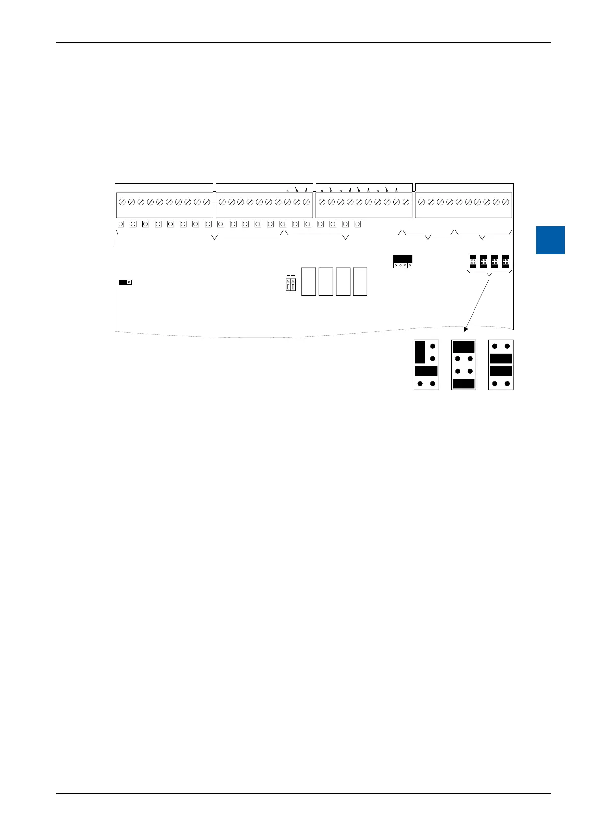
LEDs and connection terminals
Theterminalnumberingreferstotheuseofthemoduleonsockets1 … 4(top)on
thePCD2.Ifthemoduleisinstalledonsockets5 … 8(bottom),thevalue64must
be added to the addresses given. When using the module in the PCD2.C100
expansion housing, the same logic applies, with the value 128 to be added to the
‘top’ and 192 to the ‘bottom’.
A200
Factorysettings: E0 … E15 Sourceoperation: Q
A32 … A35 Voltage: 0 … 10V“U”
E48 … E51 Voltage: 0 … 10V“U”