Saia-Burgess Controls AG
Manual I/O-modules for PCD1 │ PCD2 series │ Document 27-600 – Release ENG09 │ 2019-05-01
5-68
I/O modules PCD1|PCD2
PCD2.W3x0
5
Timeconstantofinputlter: W300: typically 10.5 ms
W310: typically 12.4 ms
W340 V: typically 7.8 ms
C: typically 24.2 ms
T: typically 24.2 ms
W350: typically 16.9 ms
W360: typically 16.9 ms
Internal current consumption:
(from +5 V bus)
< 8 mA for all module types
Internalcurrent consumption:
(from V+ bus)
W300, 310 < 5 mA
W340, 360 < 20 mA
W350 < 30 mA
External current consumption: 0 mA
Terminals:
Pluggable 10-pole screw terminal block
(4 405 4847 0), for wires up to 1.5 mm²
*)No negative input voltage should be applied on these modules.
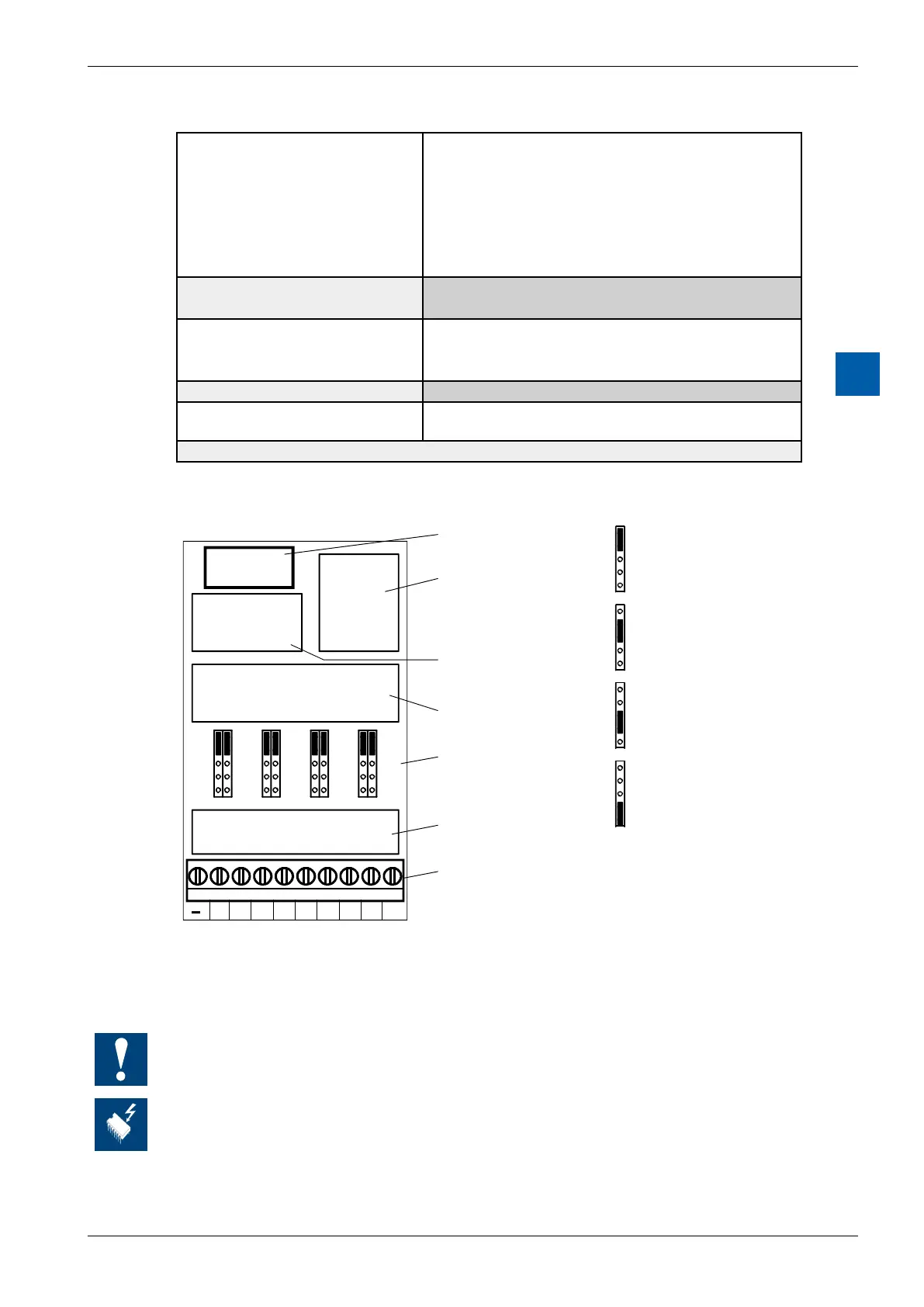
Terminals
9 8 7 6 5 4 3 2 1 0
+E6
+E7 +E4+E5 +E2+E3 +E0+E1
E7 E6 E5 E4 E3 E2 E1 E0
T
V/4
V
C
T
V/4
V
C
T
V/4
V
C
T
V/4
V
C
T
V/4
V
C
Bus interface
A/D converter and
Voltage reference
Amplifier (OP-AMP)
Jumper für working
Mode selection
(PCD2.W340 only)
Input filter
Screw terminals
COM
T
V/4
V
C
T
V/4
V
C
T
V/4
V
C
T
V/4
V
C
Position 'T': Pt/Ni 1000
Position 'V/4': (0 .. +2.5V)
Position 'V': 0 .. +10V
Position 'C': 0 .. 20 mA
Jumper positions for selecting working mode
PCD2.W340only;ontheothermoduletypestheworkingmodesarexed
All inputs set for temperature (position T) must be wired. All unused inputs (with
the W340) must be adjusted to current range ‘C’ or voltage range ‘V’.
Changing the jumpers
On this circuit board there are components that are sensitive to electrostatic
discharges. For further information, refer to Appendix A1, “Icons”.