Multi-speed parameter group 04
PARAMETER DESCRIPTION 104
3. When 04-16(P.121) is set to 0, there will be no cycle operation.
4. When 04-17(P.122) is 1~8, it is the section that will cycle to after the first cycle.
For example: When 04-17(P.122)=3, the cycle operation will start from speed 3 after the speed 1 to speed 8
operations have been completed.
5. When 04-18(P.123) is set to 0, the acceleration time is 01-06(P.7)and the deceleration time is 01-07(P.8).
6. When 04-18(P.123) is set to 1, the acceleration time and deceleration time are both determined by
04-35~04-42 (P.111~P.118). If any value in 04-35 (P.111) ~ 04-42 (P.118) is set to 0, the acceleration time
will still be 01-06 (P.7), 01-07 (P.8).
Manual cycle mode
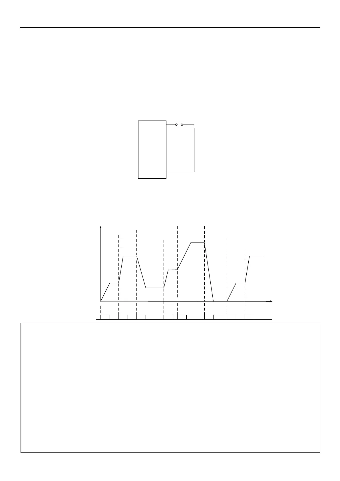
Wiring diagram for manual cycle mode
1. Connect a push button between M0 and SD.
2. After powered on, set the correspond parameter 03-03(P.80) to 35 according to the terminal. At this time, the
inverter is in standby state.
3. Operation is shown in the figure below:
Frequency
M0
ON ON ON ON ON ON ON ON
04-19
P.131
04-20
P.132
04-21
P.133
04-22
P.134
04-23
P.135
04-19
P.131
04-20
P.132
0
Time
Note:1. This program can run 8 speeds at most, which can be set by 04-19~04-26(P.131~P.138).
2. Settings for parameters 04-15~04-18(P.100、P.121~P.123)、04-27~04-42(P.101~P.118) are only for the
programmed operation mode not manual cycle mode. For the acceleration and deceleration time of manual
cycle mode, please refer to 01-06(P.7), 01-07(P.8), 01-22(P.44), 01-23(P.45).
3. If any segment is set to zero, inverter will return to standby state when run to this segment. This means that
when this mode is selected, 04-19(P.131) cannot be 0. As shown in the above diagram, if 04-24(P.136) is 0,
regardless of the values of 04-25(P.137) and 04-26(P.138), inverter will stop running when the switch is
pressed for the sixth time.
4. Manual cycle function rotation direction is single direction, which has nothing to do with the operation direction
parameter 04-16(P.121) of each speed in the programmed operation mode, and has nothing to do with STF
and STR signals.
5. For 04-35~04-42(P.111~P.118) please refer to acceleration and deceleration time increments parameter
01-08(P.21).

 Loading...

