Digital input/ output parameter group 03
PARAMETER DESCRIPTION 94
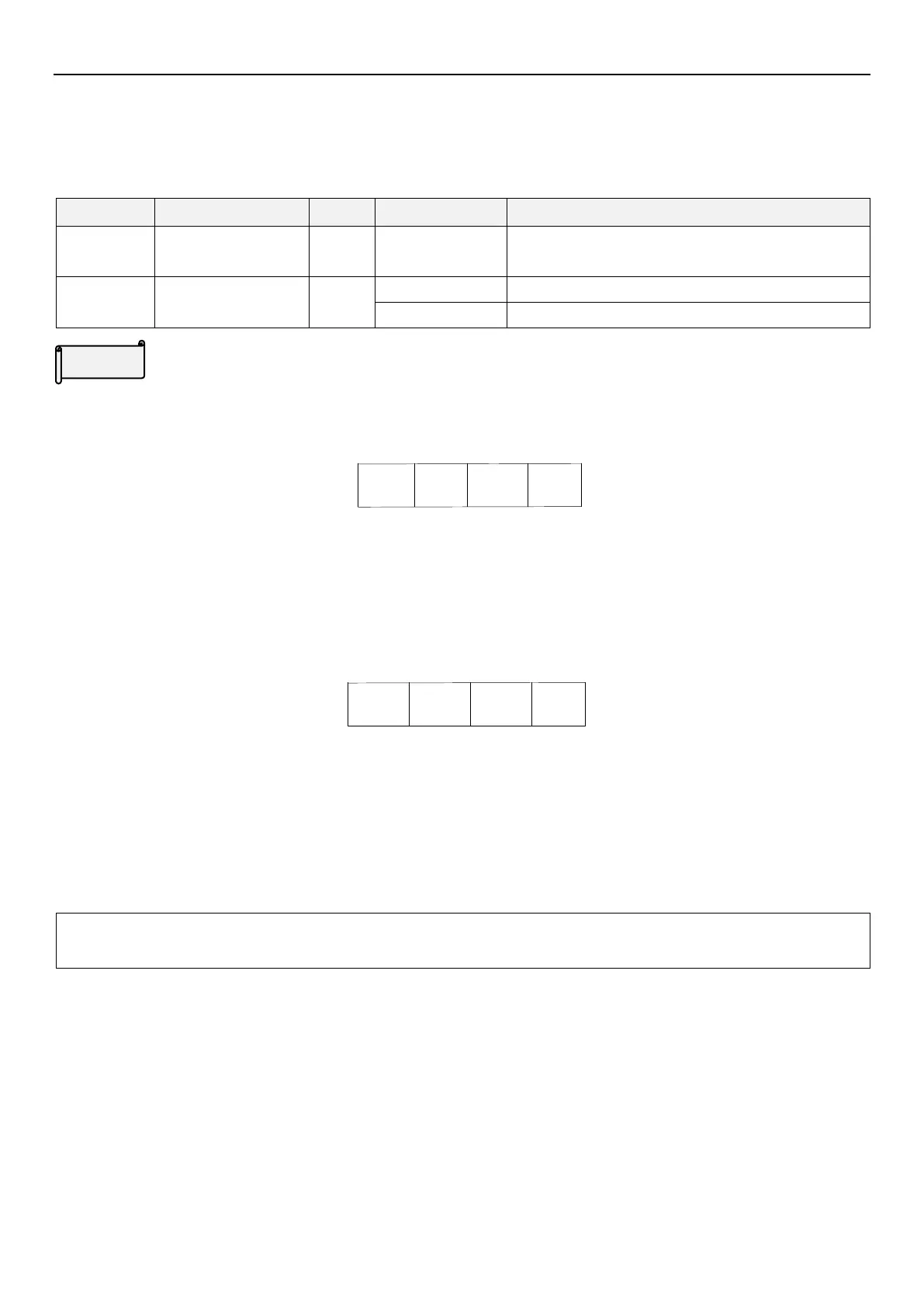
5.4.3 Terminal logic selection
The function is bits-setting, if the bit shows 1, it means that the action of multi-function digital input terminal is
negative logic; otherwise, it means that the action is positive logic.
Terminal A-C output positive logic
Terminal A-C output negative logic
Digital input/output logic
The definition of each bit of 03-14(P.87) is as follows:
For example: A three-wire control type needs the function of STOP to be kept open (negative logic). So if set
03-03(P.80)=31, take M0 terminal as three-wire control STOP function, and 03-03(P.80)=0, 03-01(P.84)=1, and
take STF and STR terminals as default positive/negative logic function, the parameter of 03-14(P.87) should be
set as follows:
So (03-14)P.87 =0×2
3
+ 1×2
2
+ 0×2
1
+ 0×2
0
= 4
The usage of 03-15(P.88):
For example: 03-11(P.85)=0 (inverter is running and detecting), if set 03-15(P.88) to 0 (positive logic), when inverter
runs, multi-relay is on. When inverter stops, multi-relay is off; if set 03-15(P.88) to 2 (negative logic), when inverter
runs, multi-relay is off, and when the inverter stops, multi-relay is on.
Note: When “STF” and “STR” terminals are set as negative logic, but signal is not connected with SD, with power on,
inverter will output and drive motor. So it is dangerous, please pay attention to it.

 Loading...

