Analog input and output parameter group 02
PARAMETER DESCRIPTION 79
5.3.1 Proportional linkage gain
This function is used to multiply frequency command from external analog input terminal. When multiple inverters
are running in proportion, it is effective to use this function to fine-tune the frequency command from master
inverter to slave inverter.
Proportional linkage
gain
Proportional linkage gain
When output frequency is lower than 01-01(P.2), it is equal to lower limit frequency 01-01(P.2). When output
frequency is higher than 01-00(P.1), it is equal to upper limit frequency 01-00(P.1).
After multiplying the setting frequency by 02-06(P.185) value, add and subtract can be performed as follows:
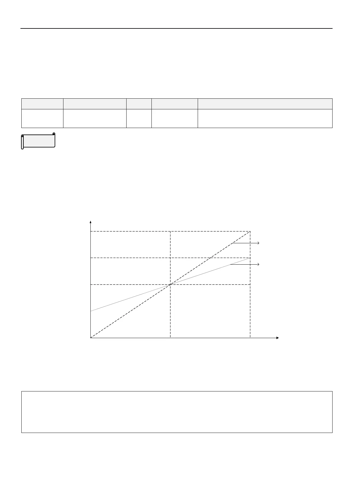
For example: When the setting frequency is 50Hz, 02-06(P.185)=50% and the external analog input signal is
0~10V.
25HZ
0V 5V 10V
50HZ
75HZ
100HZ
The target frequency
Terminal 3-5 voltage
input
02-06
P.185)=100%
02-06
P.185)=50%
In the above figure, when 0V is given, the target frequency is 50Hz - (50Hz × 50%) = 25Hz;
when 5V is given, the target frequency is 50Hz - (50Hz × 0%) = 50Hz;
when 10V is given, the target frequency is 50Hz + (50Hz × 50%) = 75Hz.
Note: 1. For proportional linkage signal input, please refer to the description of parameter 02-07 (P.240).
2. When use terminal 3-5 analog (voltage/current) signal as proportional linkage signal input terminal, please
refer to parameter 02-20(P.17);for the setting of external analog signal frequency range, please refer to
parameter 02-21(P.39)。

 Loading...

