Analog input and output parameter group 02
PARAMETER DESCRIPTION 80
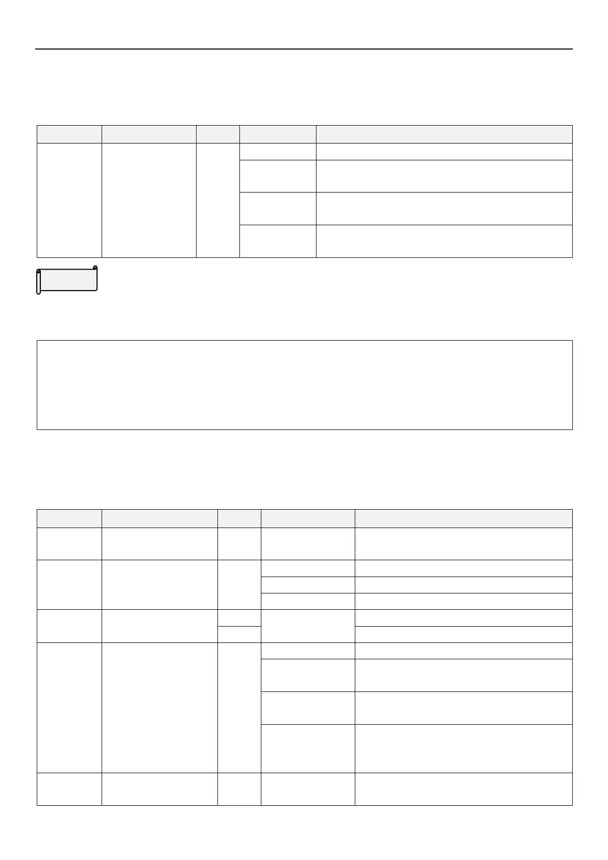
5.3.2 Auxiliary frequency
Frequency can be adjusted and synthesized flexibly to meet the different control requirements in different
scenarios.
Output frequency = basic frequency + auxiliary frequency
(given by terminal 3-5)
Output frequency = basic frequency - auxiliary frequency
(given by terminal 3-5)
Output frequency = proportional linkage signal (given by
terminal 3-5)
Auxiliary frequency
When output frequency is lower than 01-01(P.2),it equals to lower limit frequency 01-01(P.2). When output
frequency is higher than 01-00(P.1), it equals to upper limit frequency 01-00(P.1).
Note: 1.Basic frequency command is given by keypad, communication or multi-speed terminal.
2. For proportional linkage signals, please refer to the description of parameter 02-06(P.185).
3. When use terminal 3-5 analog (voltage/current) signal as proportional linkage signal input terminal, please
refer to parameter 02-20(P.17). For the setting of external analog signal frequency range, please refer to
parameter 02-21(P.39).
5.3.3 Terminal 3-5 signal selection and processing
Select terminal 3-5 signal specification and frequency compensation function.
Terminal 3-5 signal range
selection
Signal sampling range from 4~20mA.
Signal sampling range from 0~10V.
Signal sampling range from 0~5V.
Terminal 3-5 maximum
operation frequency
50Hz system (00-24(P.189)=1)
60Hz system (00-24(P.189)=0)
Terminal 3-5 disconnect
selection
Inverter decelerates to 0Hz, multi-function digital
output terminal set off alarm
Inverter stops immediately, and keypad displays
“AErr” alarm
Inverter runs continuously according to the
frequency command before disconnection. Digital
output terminal will set off alarm.
Terminal 3-5 minimum
input current/ voltage

 Loading...

