Terminal wire arrangement
INVERTER INTRODUCTION 30
3.7.5 Control circuit
Control terminal name
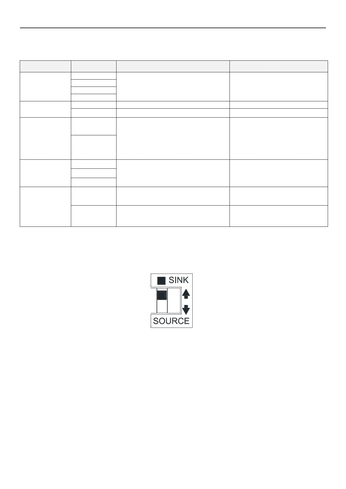
Switching SINK/SOURCE control logic
The multi-function digital input terminals on SC3 series inverter can be switched between sink and source by the toggle
switch. The diagram is as follows:
No matter which mode the multi-function digital input terminal is in, all of them can be considered as a simple switch.
If the switch is “「 on」," the control signal will be apply into the terminal. If the switch is “「 off」,” the control signal is shut
off.
If "Sink Input” mode is selected, when the multi-function digital input terminal is short-circuited to SD or connected to an
external PLC, the function of this terminal is valid. In this mode, the current flows from the corresponding terminal when
it is short. Terminal “SD” is common terminal of the contact input signals. When the output transistor is powered by an
external power supply, use PC terminal as a common terminal to prevent malfunction due to leakage current.
These 4 are multi-function control
terminals, can switch between
SINK/SOURCE.
Input impedance:4.7 kΩ
Action current :5mA( when 24VDC)
Voltage range:10~28VDC
Maximum frequency :1kHz
Multi-function relay output terminals.
A-C is normal open contact, C is common
terminal.
Maximum voltage:30VDC or
250VAC
Maximum current:
Resistor load 5A NO/3A NC
Inductance load 2A NO/1.2A NC
(cosΦ=0.4)
RS485, optical coupling isolation
RJ45 and “DA+/DB-” won’t work at the
same time
Highest rate:115200bps
Longest distance:500m
COM terminal for STF, STR, M0, M1,3
(SINK)
COM terminal for STF, STR, M0, M1
(SOURCE)

 Loading...

