PID parameter group 08
PARAMETER DESCRIPTION 137
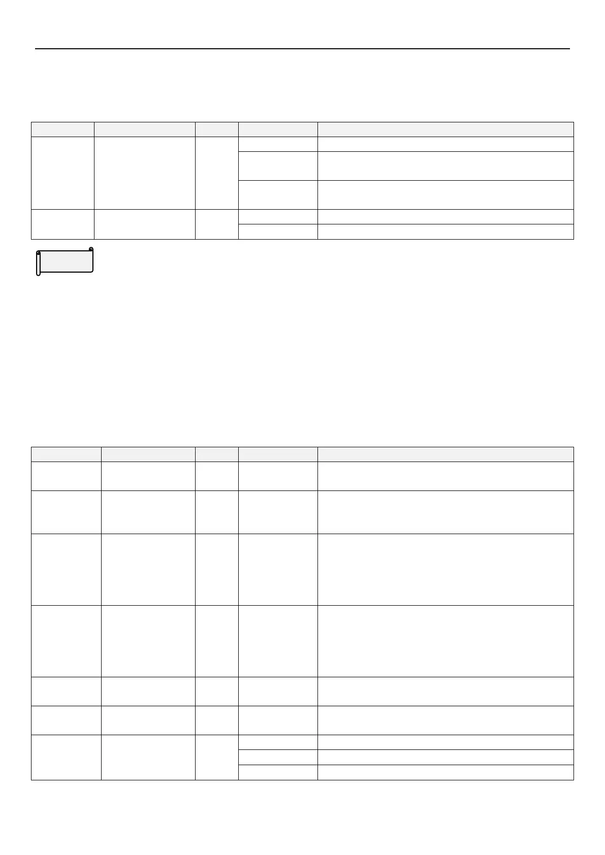
5.9.1 PID function selection
Inverter can control flow, volume or pressure by PID control. By using parameter setting as target source, and with
analog signal as feedback source, it forms a closed loop control system.
Target depends on 08-03(P.225),feedback depends on 3-5
terminal current/input voltage
Target value is set by multi-speed value, and feedback from
terminal 3-5 current/voltage input
PID feedback control
method
Negative feedback control
Positive feedback control
PID function selection
During PID control, frequency displayed on screen is inverter output frequency.
For terminal 3-5 input signal filtering please refer to parameters 02-10(P.60).
When 08-00(P.170) set parameter =3, the 16 target pressure value are set by digital input terminal RL , RM, and
combination of RH & REX. The default target pressure value is set by 08-03(P.225) parameter. The 1st -15th are
set by multi-speed parameter 04-00(P.4)~04-02(P.6)、04-03(P.24)~04-06(P.27)、04-07(P.142)~04-14(P.149).
Eg: When 08-00(P.170)=3,04-02(P.6)=25.00,08-43(P.251)=100.0,RL terminal is ON, PID target pressure ratio is 25%.
5.9.2 PID parameter group
By setting PID parameters users can realize automatic adjustment of process control.
PID target value
from keypad
When 08-00 (P.170) is set to 2, the target value is set by
08-03(P.225)
This gain determines the proportion controller’s response on
feedback deviation. The greater the gain, the faster the
response. Gain set too high will cause vibration.
This parameter determines integral controller’s integral time.
When integral gain is too high, integral effect will be too weak
to eliminate steady state deviation. When integral gain is
rather small, the system vibration time will increase, and too
small integral gain will cause system unstable.
This gain determines deviation controller’s response to
deviation change rate. Appropriate deviation time can reduce
overshooting and vibrating between proportion controller and
integral controller. Deviation time set too long will cause
system vibration.
Alarm and continue operation

 Loading...

