Terminal wire arrangement
INVERTER INTRODUCTION 28
3.7.2 Main circuit wiring and terminal specification
Terminal
screw
specifications
Tightening
torque
(Kgf.cm)
Recommended wiring specification(mm2)
Recommended wiring specification (AWG)
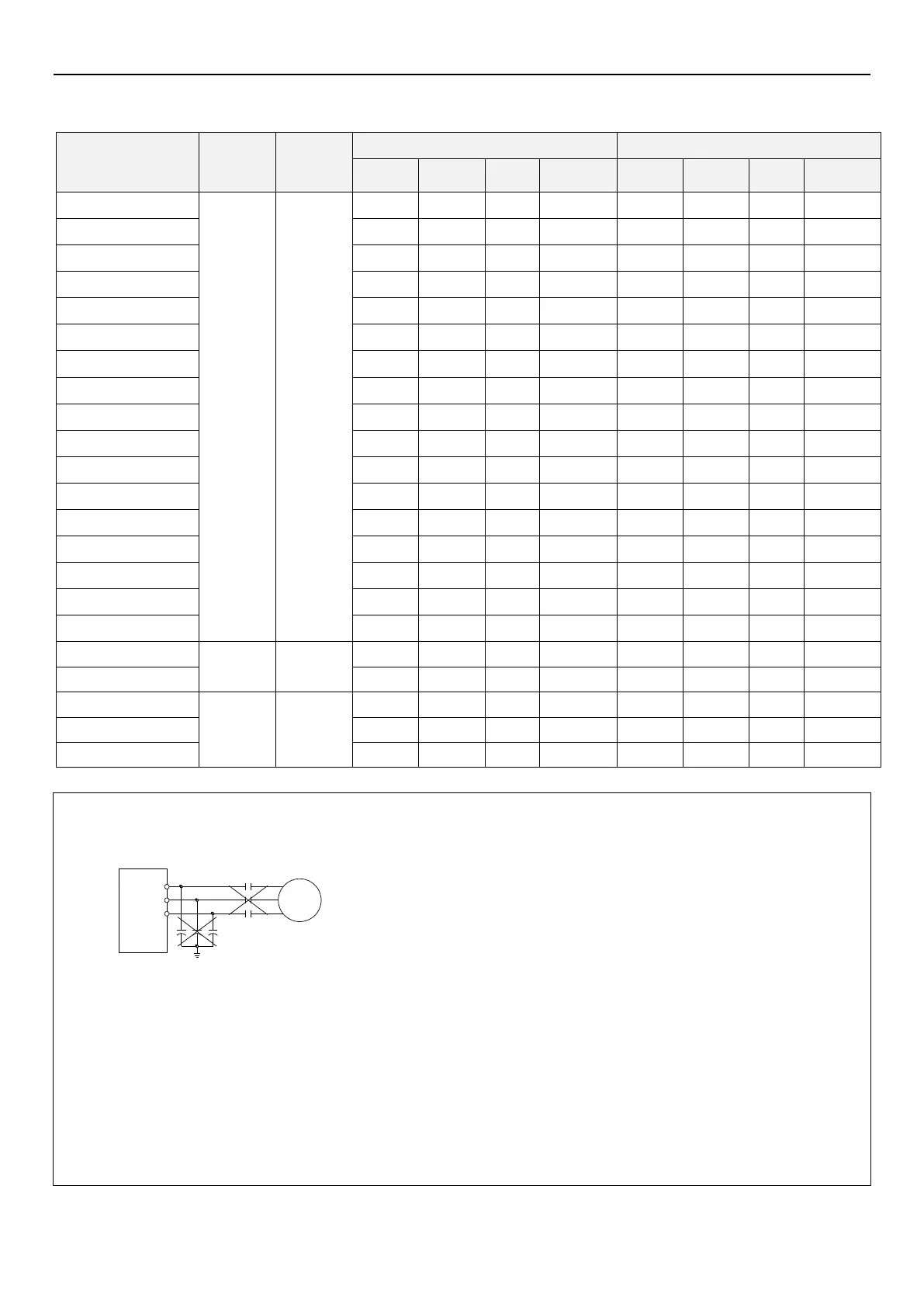
Note:1. Do not connect power wire to motor terminals (U/T1)(V/T2)(W/T3) on inverter, otherwise it will cause damage.
2. Do not add phase capacitor, surge absorber or magnetic contactor on the output side of the inverter.
U/T1
V/T2
W/T3
Inverter
Electromagnetic
contactor
Motor
Phase
capacitor
3. Do not use "magnetic contactor" or "no fuse switch" to start and stop the motor.
4. Please do grounding for the inverter and motor to avoid electric shock.
5. For specifications of no-fuse breaker and magnetic contactor, please refer to section 3.6.2.
6. If the distance between the inverter and motor is long, please use thick wires, make sure wire voltage drop is under
2V (wire length below 500 meters).
7. Use "insulation crimp sleeve " for power supply side and load side connection.
8. After the power is cut off, there is still high voltage between the terminals of the main circuit within a short period of
time. Please do not touch the terminals within 10 minutes to avoid electric shock.

 Loading...

