Basic Parameter Group 01
PARAMETER DESCRIPTION 66
5.2.3 Acceleration/deceleration time setting
Use this function to set motor acceleration/deceleration time.
Acceleration/ deceleration
curve selection
Linear acceleration /deceleration curve
S shape acceleration /deceleration curve 1 (Note 1)
S shape acceleration /deceleration curve 2 (Note 2)
S shape acceleration /deceleration curve 3 (Note 3)
7.5K/11KF and above model
Acceleration/ deceleration
time increments
Acceleration/ deceleration
reference frequency
50Hz system setting (00-24(P.189)=1)
60Hz system setting(00-24(P.189)=0)
Acceleration/deceleration curve selection
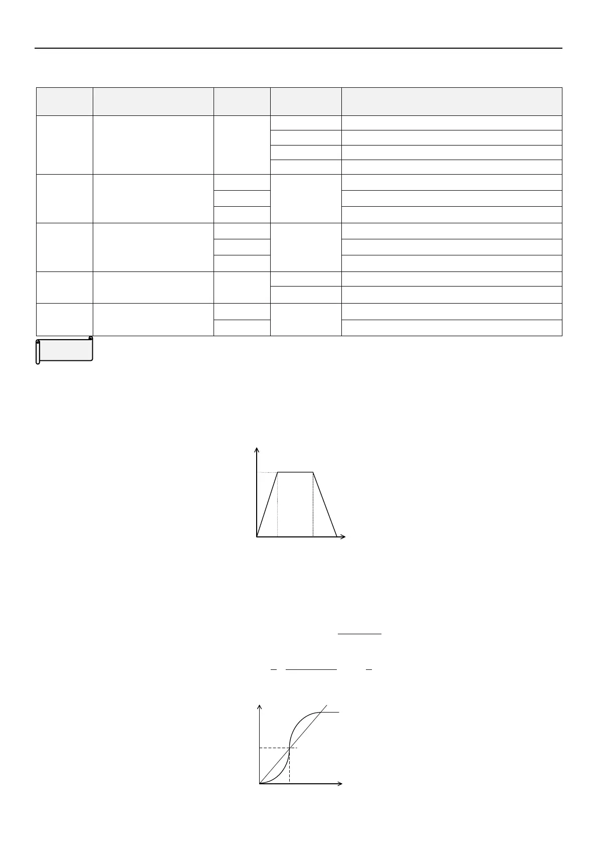
Linear acceleration /deceleration curve(01-05(P.29)=0)
An acceleration slope is formed by the combination of 01-06(P.7) and 01-09(P.20). A deceleration slope is formed
by the combination of 01-07(P.8) and 01-09(P.20).
When the target frequency varies, it increases according to the “acceleration slope” or decreases according to the
“deceleration slope” linearly. See the figure below:
Output frequency
Time
01-06(P.7)
01-07(P.8)
Acceleration slope
Deceleration slope
01-09(P.20)
S shape acceleration /deceleration curve 1(01-05(P.29)=1)
An acceleration slope is formed by the combination of 01-06(P.7) and 01-03(P.3). A deceleration slope is formed
by the combination of 01-07(P.8) and 01-03(P.3).
The acceleration / deceleration curve has an S-shape change according to the “acceleration / deceleration slope”.
The S-shape equation between 0 and 01-03 (P.3) is:
03(P.3)-01)]
06(P.7)-01
90
cos(1[
t
f
The S-shape equation above 01-03 (P.3) is:
06(P.7)-01
9
5
03(P.3)-01
06(P.7)-01
9
4
2
2
ft
t = time; f = output frequency
Acceleration slope
Output frequency
01-06(P.7)
01-03(P.3)
Time

 Loading...

