Basic Parameter Group 01
PARAMETER DESCRIPTION 67
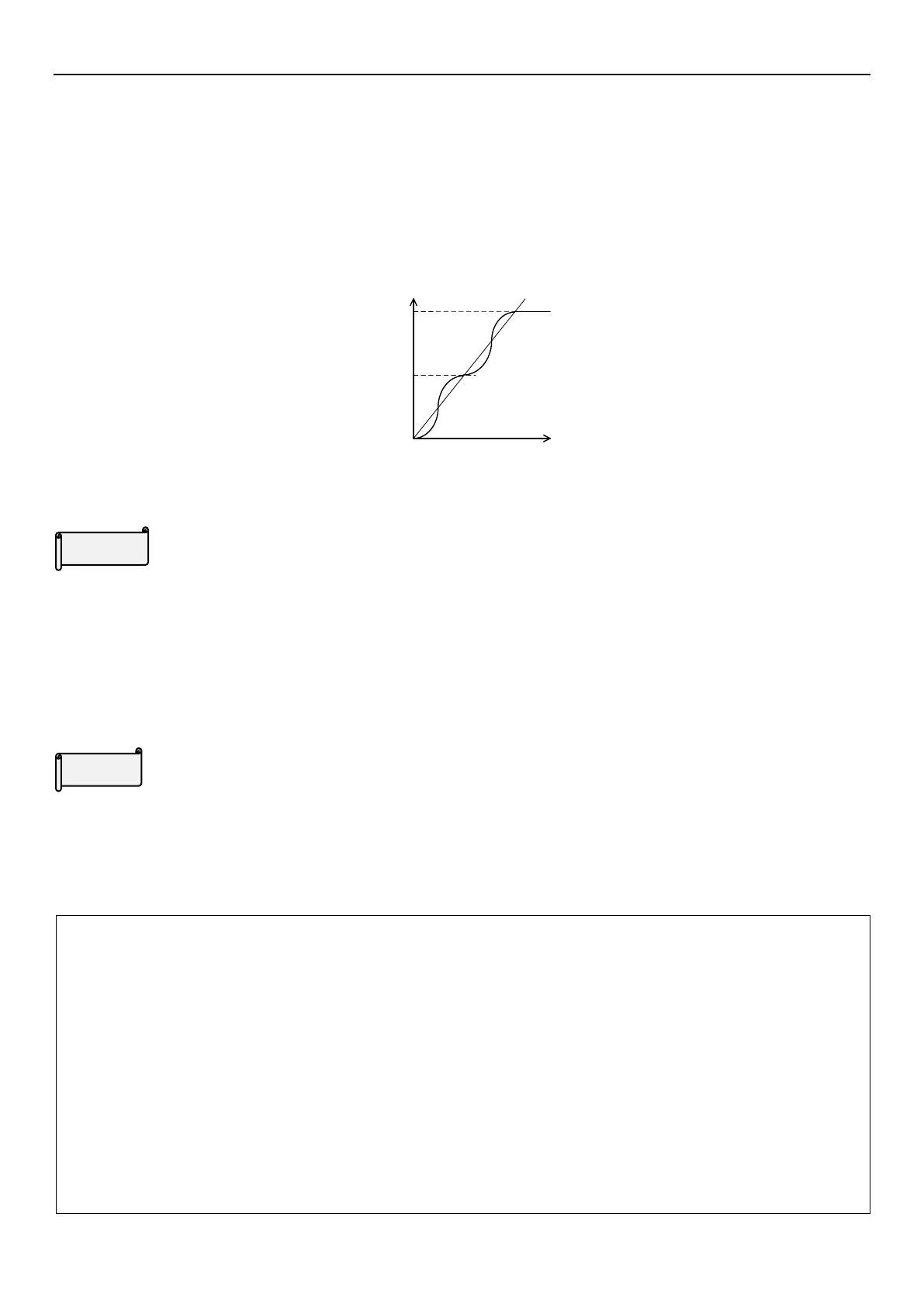
S shape acceleration /deceleration curve 2(01-05(P.29)=2)
An acceleration slope is formed by the combination of 01-06(P.7) and 01-09(P.20). A deceleration slope is formed
by the combination of 01-07(P.8) and 01-09(P.20).
When the target frequency varies, the acceleration increases S-shape according to the “acceleration slope”. The
deceleration decreases S-shape according to the “deceleration slope”. As shown in the figure below, when
frequency is adjusted from f0 to f2, it accelerates S-shape once, and the time is 01-06(P.7) × (f2-f0) / 01-09(P.20).
Then if the frequency is adjusted from f2 to f3, it accelerates S-shape the second time, and the time is 01-06(P.7) ×
(f3-f2) / 01-09(P.20).
Acceleration slope
Time
Output frequency
f0
f2
f3
S shape acceleration /deceleration curve 3(01-05(P.29)=3)
Please refer to 5.2.12 S pattern time setting.
Acceleration/deceleration time increments
When 01-08(P.21)=0, minimum acceleration / deceleration time(01-06(P.7), 01-07(P.8), 01-14(P.16), 01-22(P.44),
01-23(P.45), 01-36~01-39(P.255~P.258), 04-35(P.111)~04-42(P.118), 10-27~10-28(P.238~P.239) increment is
0.01s.
When 01-08(P.21)=1, minimum acceleration / deceleration time(01-06(P.7), 01-07(P.8), 01-14(P.16), 01-22(P.44),
01-23(P.45), 01-36~01-39(P.255~P.258), 04-35(P.111)~04-42(P.118), 10-27~10-28(P.238~P.239) increment is
0.1s.
Acceleration / deceleration reference frequency
When the output frequency of the inverter is accelerated from 0Hz to 01-09(P.20), the required time is defined as
“acceleration time”.
When the output frequency of the inverter is decelerated from 0Hz to 01-09(P.20), the required time is defined as
“deceleration time”.
Note: 1. S shape acceleration /deceleration curve 1 is used when acceleration/deceleration is required in a short time
in high-speed area equal to or higher than the base frequency, such as spindle motor.
2. S shape acceleration /deceleration curve 2 can effectively reduce motor vibration during the acceleration /
deceleration, and thus prevent the belts and gears from failing.
3. S shape acceleration /deceleration curve 3 is used to start the inverter gradually without impact.
4. Please refer to Section 5.2.10 second function for the second acceleration/deceleration time.
5. When RT is “on”, the second function is on. For the operation characteristics of the motor, please refer to
Section 5.2.10 Second function. RT mentioned in this section is the function name of the “multi-function
digital input terminal”. Please refer to 03-00(P.83)、03-01(P.84)、03-03(P.80)、03-04(P.81) for function
selection and purposes of the multi-function digital input terminal. For related wiring, please refer to Section
3.7 Terminal wire arrangement.

 Loading...

