Operation modes of inverter
BASIC OPERATION 37
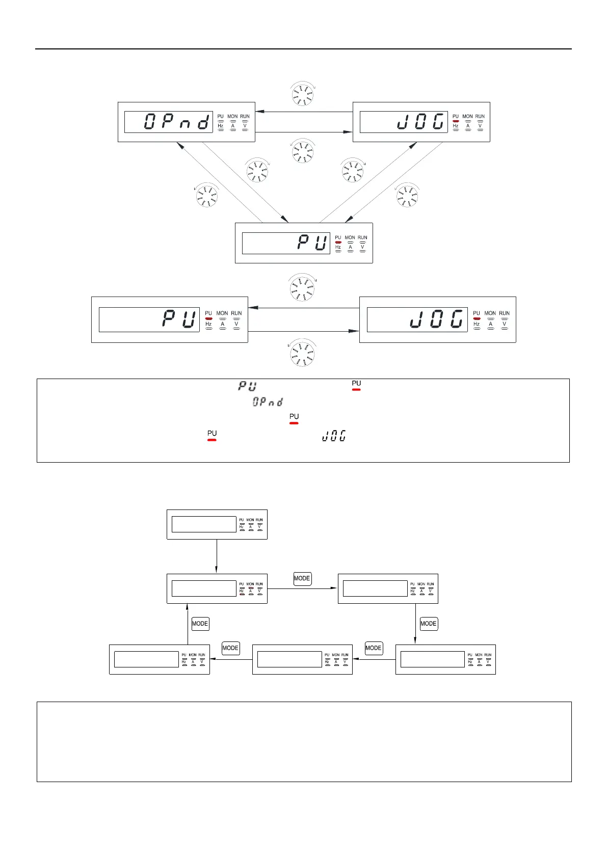
4.2.1 Flow chart for switching operation mode
4.2.2 Flow chart for switching built-in keypad working mode
5 C3
Wait 2s
.
0 0 0
.
0 0 0
OPn dHEl P 0 0- 0 0
Note: 1. Please refer to section 4.2.3 for detailed operation steps under monitoring mode.
2. Please refer to section 4.2.4 for detailed operation steps under frequency setting mode.
3. Please refer to section 4.2.5 for detailed operation steps under parameter setting mode.
4. Please refer to Section 4.2.1 for detailed operation steps under switching operation mode.
5. Please refer to Section 4.2.6 for detailed operation steps under HELP mode.
Note: 1. In “PU mode”, keypad screen displays and the indicator in will light up.
2. In “External mode”, keypad screen displays .
3. In “Combined mode 1, 2, 3, 4, or 5”, the indicator in will flicker.
4. In “JOG mode”, the indicator in will light up, and show when motor is not running.
5. No flow chart when 00-16(P.79) is set to =2, 3, 4, 5, 6, 7 or 8 since the operation mode will not switch.

 Loading...

