System parameter group 00
PARAMETER DESCRIPTION 55
Note: 1. The “output frequency” here is the value after slip compensation.
2. The multi-function display function is implemented in the monitor voltage mode. For switching to monitor voltage mode,
refer to section 4.2.3.
3. Digital terminal input state detail
4. Digital terminal output state detail
Keypad monitoring selection
Display current pressure and feedback pressure of the constant pressure system in percentage (00-06(P.110)=3)
The screen shows two sections. A decimal point is used to separate the boundaries, on the left is the target
pressure and on the right is the feedback pressure of the constant pressure system in percentage.
As shown in this figure: , “20” means the target pressure of the constant pressure system is 20%,
the target value will be 20%*08-43(P.251); “30” means the feedback pressure of the constant pressure system is
30%, the feedback value will be 30%*08-43(P.251).
Displays current pressure and feedback pressure of the constant pressure system (00-06(P.110)=5)
The screen shows two sections. A space is used to separate the boundaries, on the left is the target pressure and
on the right is the feedback pressure of the constant pressure system
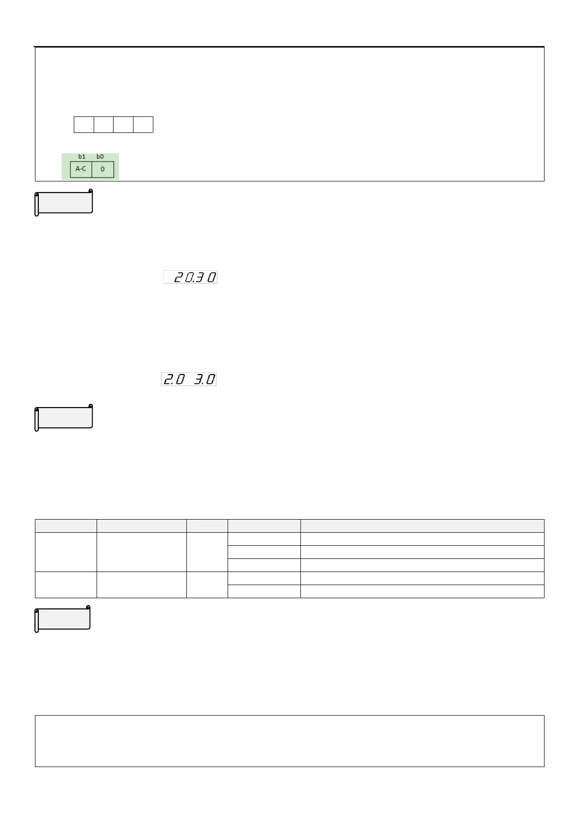
As shown in this figure: ,“2.0” means the target pressure of the constant pressure system is 2.0,
“3.0” means the feedback pressure of the constant pressure system is 3.0.
Multi-function display
The display value will show in the monitor voltage mode. Please refer to 4.2.3 for flow chart of monitoring mode.
5.1.5 Speed display
In “monitoring output frequency” mode, the screen displays corresponding machine speed.
Display output frequency(not mechanical speed)
Speed display unit
selection
Speed display unit is 0.1
Speed display
The setting value of 00-08(P.37) is the speed of motor when output frequency is 60Hz.
For example:
1. If the transmitting belt speed is 950 m/minute when the inverter output frequency is 60Hz, set 00-08(P.37) =
950.
2. After setting, in the keypad “output frequency monitor mode” , the screen will display the speed of the
transmitting belt.
Note: The machine speed on the screen is the theoretical value calculated proportionately by the inverter output
frequency and the setting value of 00-08(P.37). So there’s minute discrepancy between the displayed machine
speed and the actual one.

 Loading...

