Operation modes of inverter
BASIC OPERATION 38
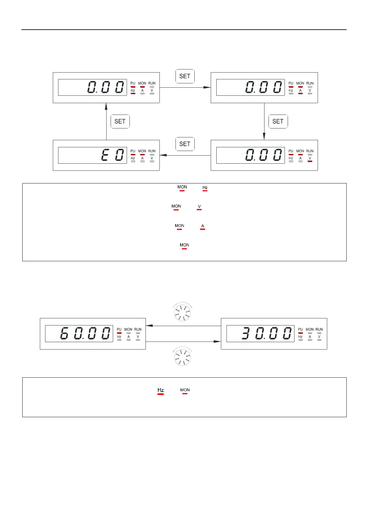
4.2.3 Operation flow chart for monitoring mode
●Take PU mode as an example:
Note: 1. In “monitoring output frequency” mode, indicator in and will light up, and the screen will display current output
frequency.
2. In “monitoring optional value” mode, indicator in and will light up, and the screen will display current optional
value. The optional value is chosen by parameter 00-07(P.161), the default setting is monitor output voltage.
3. In “monitoring output current” mode, indicator in and will light up, and the screen will display current output
current.
4. When in “browsing alarm record” mode, indicator in
will light up, and the screen will display current alarm code.
5. For alarm codes, please refer to Appendix 2.
4.2.4 Operation flow chart for frequency setting
Note: 1. Use dial to change the frequency when the inverter is running.
2. Under frequency setting mode, indicator in and will not light up.
3. When setting frequency with keypad, the set value cannot exceed the upper frequency. When high frequency is needed,
the upper frequency should be changed first.

 Loading...

