Communication parameter group 07
PARAMETER DESCRIPTION 121
Note:1. Maximum inverter connect number is determined by wiring method and impedance matching. Please set
station number value to non-zero when using Modbus protocol.
2. If communication error times exceed set value of 07-08(P.52), and 07-10(P.153) is set to 0, OPT alarm will
trigger.
3. Modbus protocol is expressed according to start bit, data bit, parity check bit and stop bit. In addition, N means
no parity check, E means 1-bit even check, and O means 1-bit odd check.
4. In Shihlin protocol, please check the settings of parameter 07-03~07-05(P.48~P.50).If 07-04(P.49) is set to
1(stop bit 2 bit),set 07-05(P.50) to 0 and select no parity check;the format of 07-03(P.48)=1, 07-04(P.49)= 07-05
(P.50)=0 is unusable.
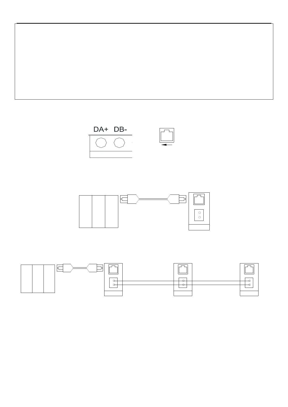
Composition and wiring of SC3 RS485 communication interface
1.
Terminal configuration of SC3 RS485 communication interface
RJ45 PIN Instruction
1,2,3,6:Reserved
4:DB-
5:DA+
7:+5V
8:GND
8
1
Cord End Terminal RJ45
2.
Communication between upper controller and a single inverter (take PLC as an example)
Number 1
PLC
Inverter 1
DA+
DB-
3.
Communication between upper controller and multiple inverters (take PLC as an example)
PLC
.....
Number 1
Inverter 1
DA+
DB-
Number 2
Inverter 2
DA+
DB-
Number n
Inverter n
DA+
DB-
4.
SC3 series inverter support Shihlin communication protocol and MODBUS communication protocol
Shihlin protocol
1. Upper controller and inverter automatically converted into ASCII code (hexadecimal) for communication.
2. Please follow the steps to perform data communication between upper controller and inverter.

 Loading...

