Communication parameter group 07
PARAMETER DESCRIPTION 123
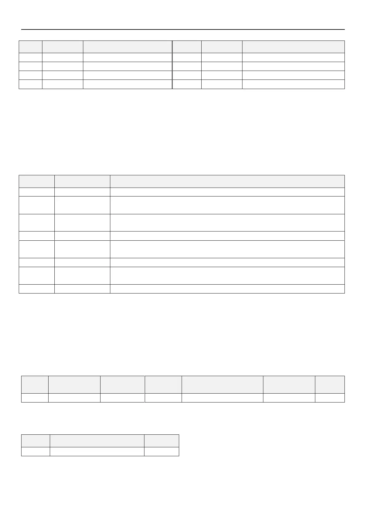
*1) Control code
*2) Waiting time set from 0 to 15 with 10ms unit. Example: set value 5 --->50ms.
*3) End symbol (CR, LF codes)
When performing data communication from upper controller to inverter, CR and LF codes at the end of message will be
automatically set according to upper controller mode. At this time, inverter must also make necessary settings to cooperate with
upper controller. If only CR is selected, only one register is occupied; If both CR and LF are selected, two registers will be
occupied.
*4) Unit: 0---> Unit 1, 1---> Unit 0.1, 2---> Unit 0.01, 3---> Unit 0.001
*5) Error code:
Communication error content
Parity check of data received by inverter is different from parity check initially set
Sum Check value calculated by inverter according to received data is different from received
Sum Check value
Communication
protocol error
Structure of the data received by inverter is incorrect; or data has not been received within
specified time; or CR and LF codes are different from those initially set
Stop bit of data received by inverter is inconsistent with stop bit initially set
When inverter is receiving data (not all data have been received yet), upper controller
transmits next data to it.
Write when inverter is running or mode setting requirements are not met
A command code that cannot be processed by inverter is specified
When setting parameters and frequencies, data outside the set range are specified
*6) When the parameter has the characteristics of 99999, the write-in or read-out of 99999 will be replaced by HFFFF
*7)Request sum check code
ASCII-converted code of the data is added in binary code, and the lower bit (lower 8 bits) of the result (summation) is converted
to ASCII 2 bits (hexadecimal), which is called SumCheck Code.
Communication example:
Example 1. Upper controller sends a forward rotation command to inverter:
Step 1: Use the upper controller to send a FA command in Format A:
Sum Check calculation:H30+H30+H46+H41+H30+H30+H30+H30+H32=H1D9, take the lower eight bits D9 to
convert to ASCII code H44 and H39
Step 2: After receive and processing the data without error, inverter will send reply to upper controller in Format C:
Inverter station number 0
Example 2. Upper controller sends a stop rotation command to inverter:
Step 1: Use upper controller to send FA command in Format A:
Inverter station
Number 0

 Loading...

