7.12.7 Drawing in points that cannot be monitored
Overview
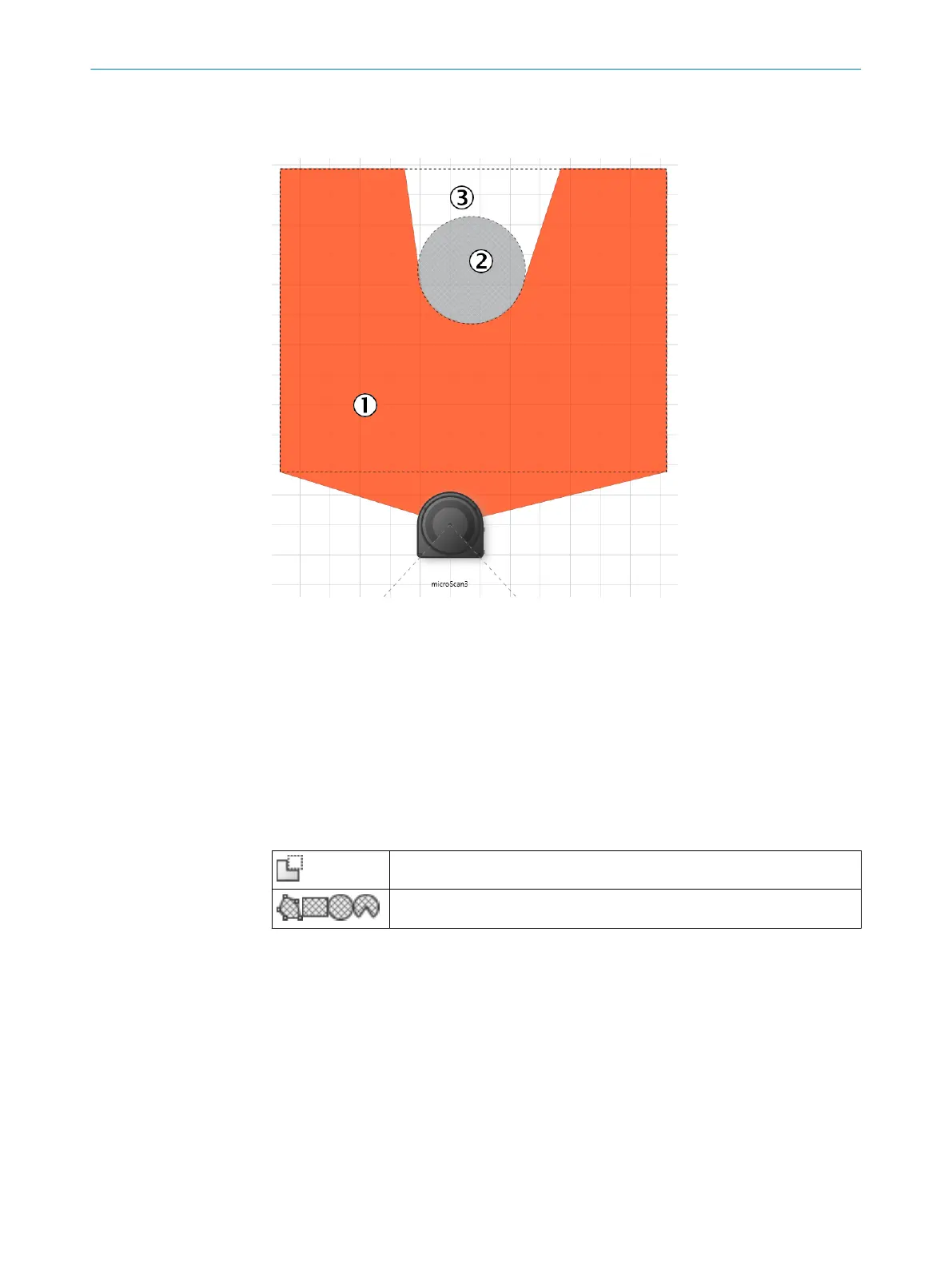
Figure 70: Area that cannot be monitored
1
Protective field
2
Marked column
3
Area that cannot be monitored
The area to be monitored is scanned radially 1. F
or this reason, shadows 3 are
formed by objects in the room 2 (support columns, separator grids, etc.). The safety
laser scanner cannot monitor these areas.
You draw objects that limit the field of view of the safety laser scanner as masked
areas.
Table 13: Mask areas
Mask areas
Hatched drawing tools
Procedure
1.
Click on the Mask areas tool.
✓
The tools you can use to draw fields are shown crosshatched.
2. Choose a drawing tool.
3. Draw the masked area.
✓
The masked area is shown in gray.
✓
The field editor shows the shadowing of the masked area.
CONFIGURATION 7
8025220/1L9Q/2023-08-14 | SICK O P E R A T I N G I N S T R U C T I O N S | microScan3 – EtherCAT®
113
Subject to change without notice