Example
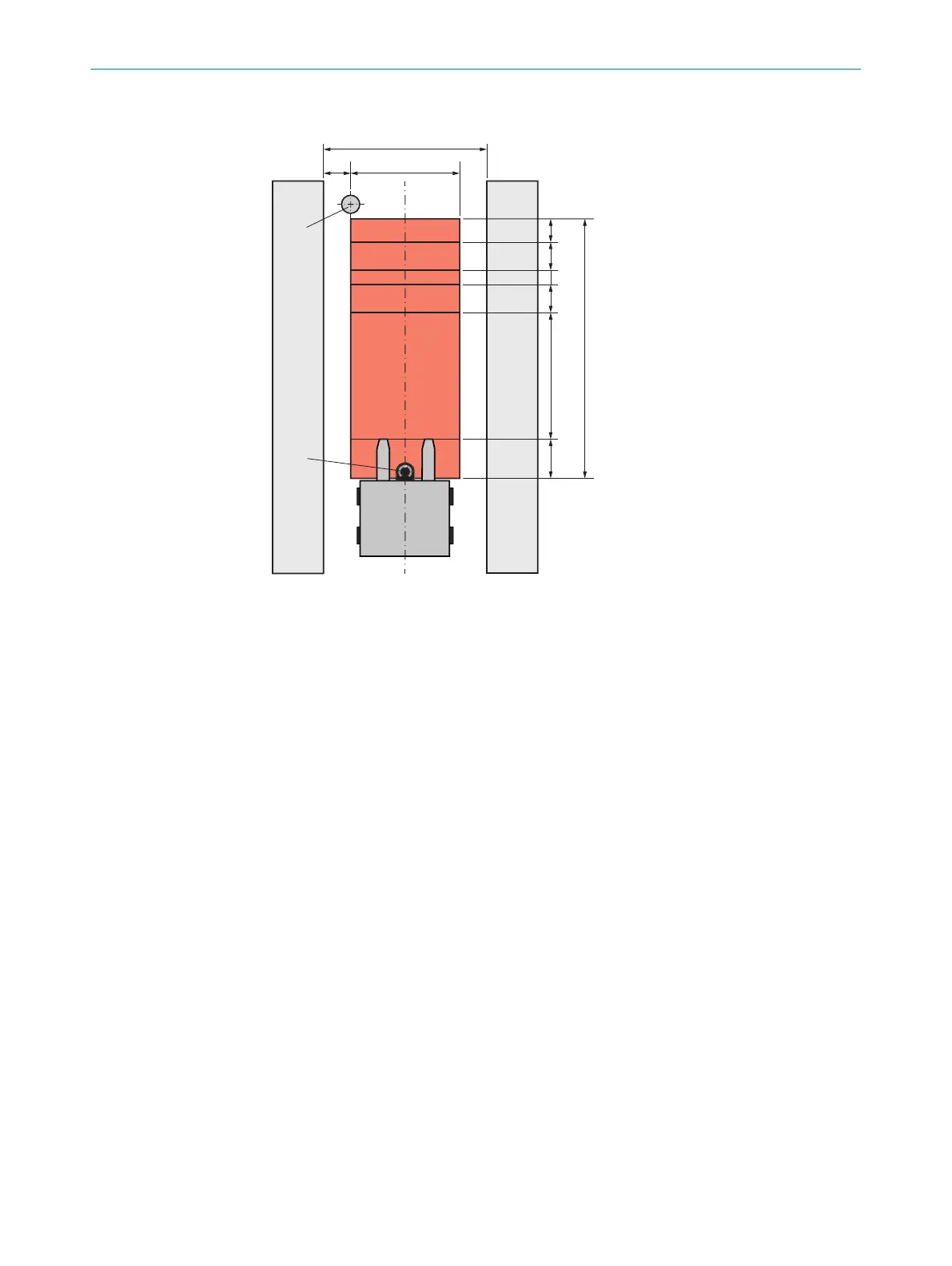
Figure 41: Protective field in narrow aisle
1
Width of the narrow aisle
2
Distance between protective field and front of the rack = distance between test object
and fr
ont of the rack
3
Protective field width
4
Rack
5
Test object
6
Safety laser scanner
7
L
SLS
= ma
ximum distance from the mounting position of the safety laser scanner to the
leading edge of the industrial truck or load
8
S
A
= s
topping distance
9
Z
B
= supplement f
or the decreasing braking force of the vehicle
ß
Z
F
= supplement f
or lack of ground clearance of the vehicle
à
Z
R
= supplement f
or reflection-related measurement errors
á
T
Z
= t
olerance zone of the safety laser scanner
â
S
L
=
protective field length
Assumed values:
•
S
A
= 3850mm
6)
•
T
Z = 100mm (device with max. protective field range 9.0m)
•
Z
R
= 350mm (reflectors (reference targets) in scan plane, due to use of collision
protection field)
•
Z
F
= 0mm (sufficient ground clearance)
•
Z
B
= 0mm (already considered in S
A
)
•
Width of the narrow aisle = 2400mm
•
Distance between safety laser scanner and front of the rack = 1,200mm
•
Distance between protective field and front of the rack: 100mm
6)
St
opping distance at maximum load = 3500mm, factor for wear of brakes = 1.1
4 P
ROJECT PLANNING
56
O P E R A T I N G I N S T R U C T I O N S | microScan3 – EtherCAT® 8025220/1L9Q/2023-08-14 | SICK
Subject to change without notice